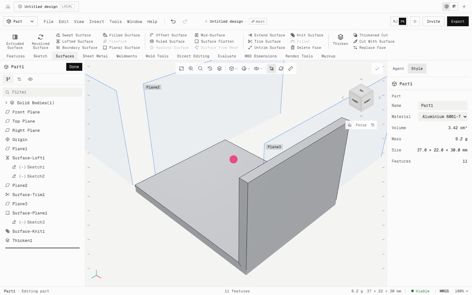
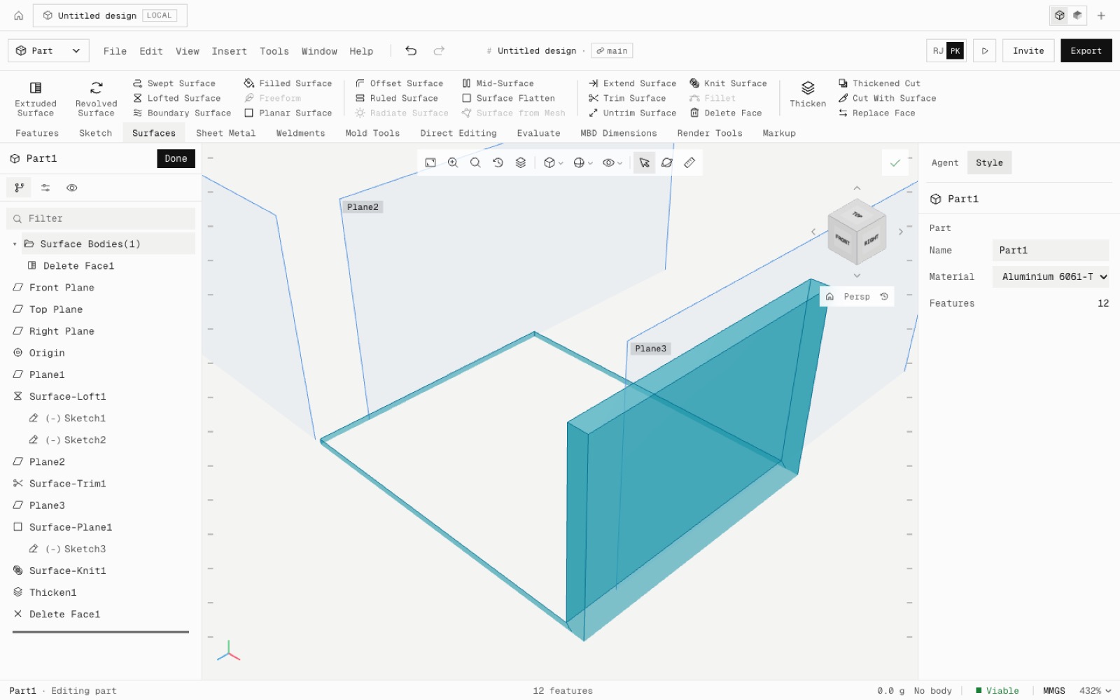
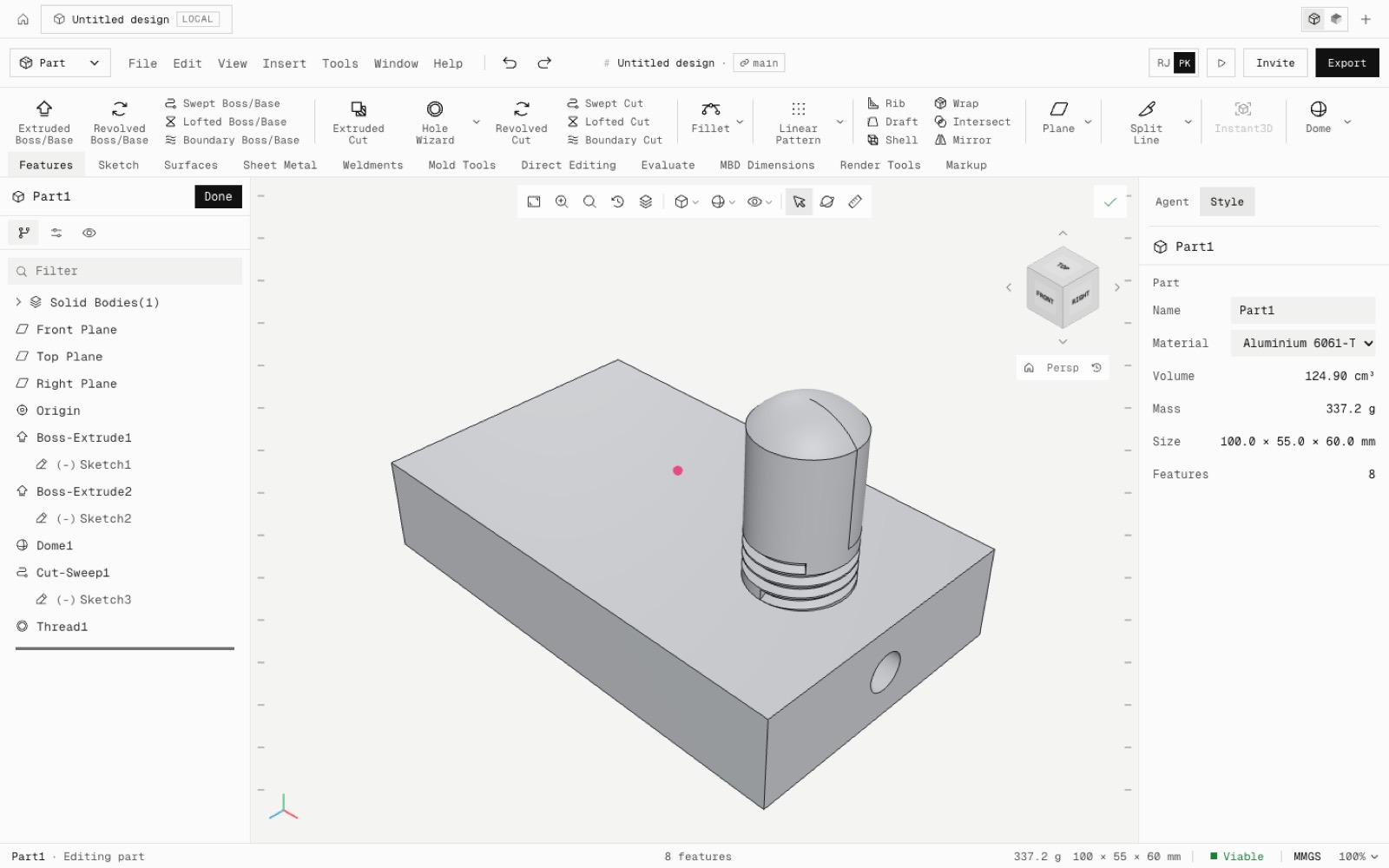
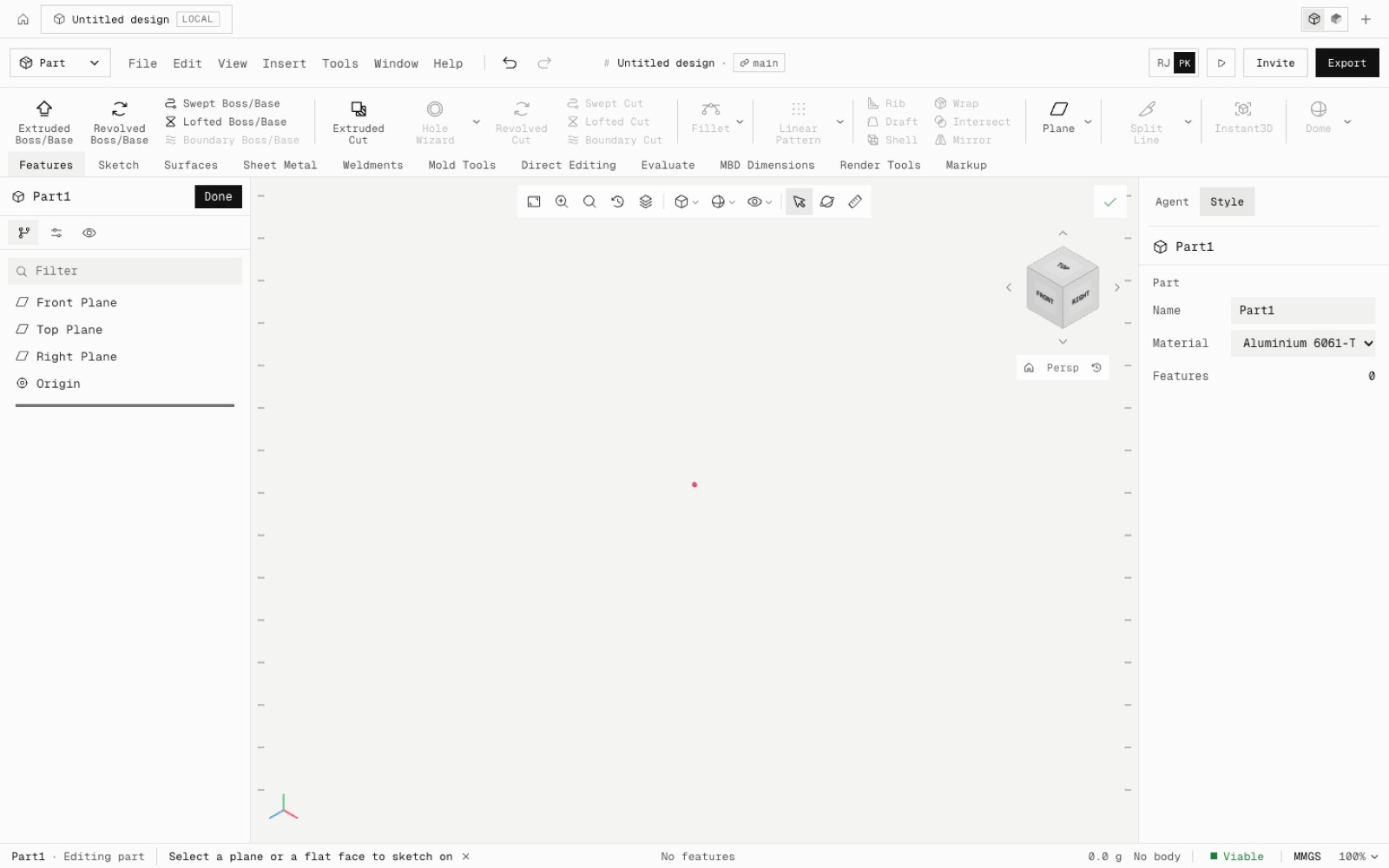
Speed/Updates

Changelog

What's new in Speed

A living record of what we ship: features, improvements and fixes across Speed.

Latest v2.89, 10 November 2026116 releasesRSS feed
Featurev2.89

Profile, delete account and a first-run welcome

Add your name and first project when you join, manage your profile from App preferences, and delete your account whenever you want.

A new Profile page holds your name and email, Log out and Delete account. Open it from App preferences or the workspace menu on the Projects page.

The Speed mark in the editor now takes you to All projects, and links from a connected AI chat always open on app.tryspeed.ai.

Added
  • Profile page
  • Delete account
  • First name, last name and project name when you first sign in
Improved
  • The Speed mark in the editor goes to All projects
  • Bottom added to the editor's view list
Fixed
  • Chats connected through the old address opened their design tab away from the main site
Shipped in
a9d3d3a
Fixv2.88

Agent edits no longer reset a part's other settings

When an agent changed one dimension of a part, the part could lose its wall thickness or tank fluid, which changed its mass.

An agent resizing a hollow part could turn it into a solid block, and resizing a tank could drop its liquid. Edits now change only what the agent asked for.

Fixed
  • A hollow part became solid after an agent resized it
  • A tank lost its fluid after an agent edited it
Shipped in
8e3bf51
Improvementv2.87

Your avatar now shows who is on the design

The avatar at the top of the right panel is now a button with your own initials. It lists who is on the design and leads to its sharing settings.

Click your avatar to see everyone with this design open. From there you can copy the project link, open Sharing settings or see who can edit.

Inviting someone by email is not built yet. Today a project opens only for its owner and members.

Improved
  • The avatar is a button you can reach with the keyboard
Fixed
  • The avatar showed the same initials for everyone
Try it

Open a saved project and click your avatar.

Open Speed
Shipped in
f7a6151
Featurev2.86

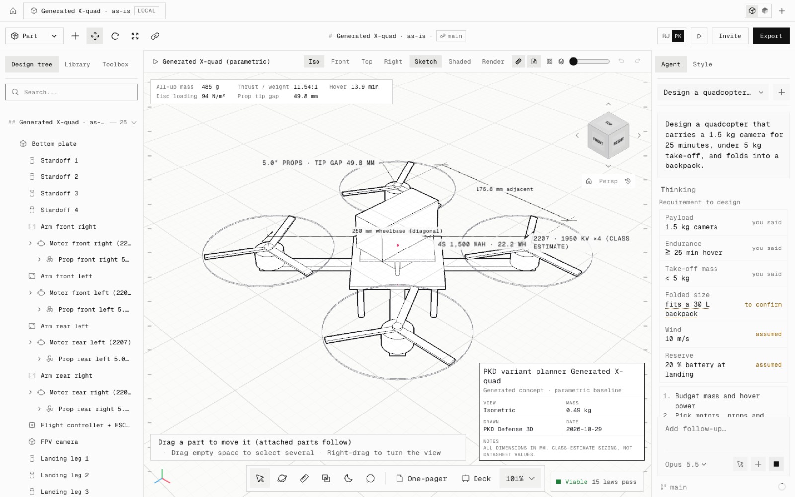
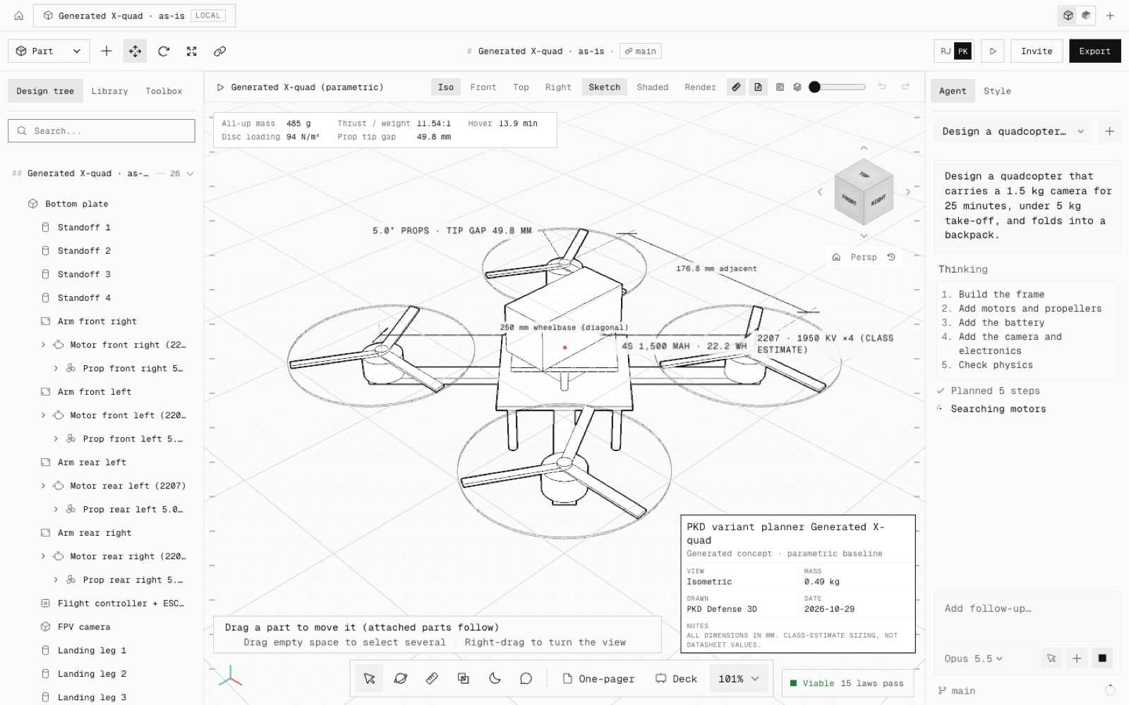
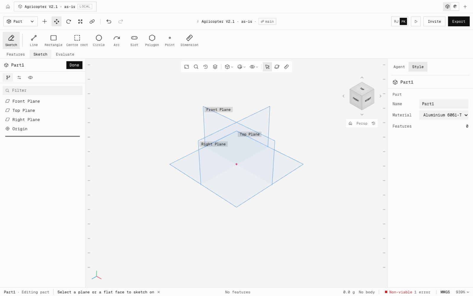
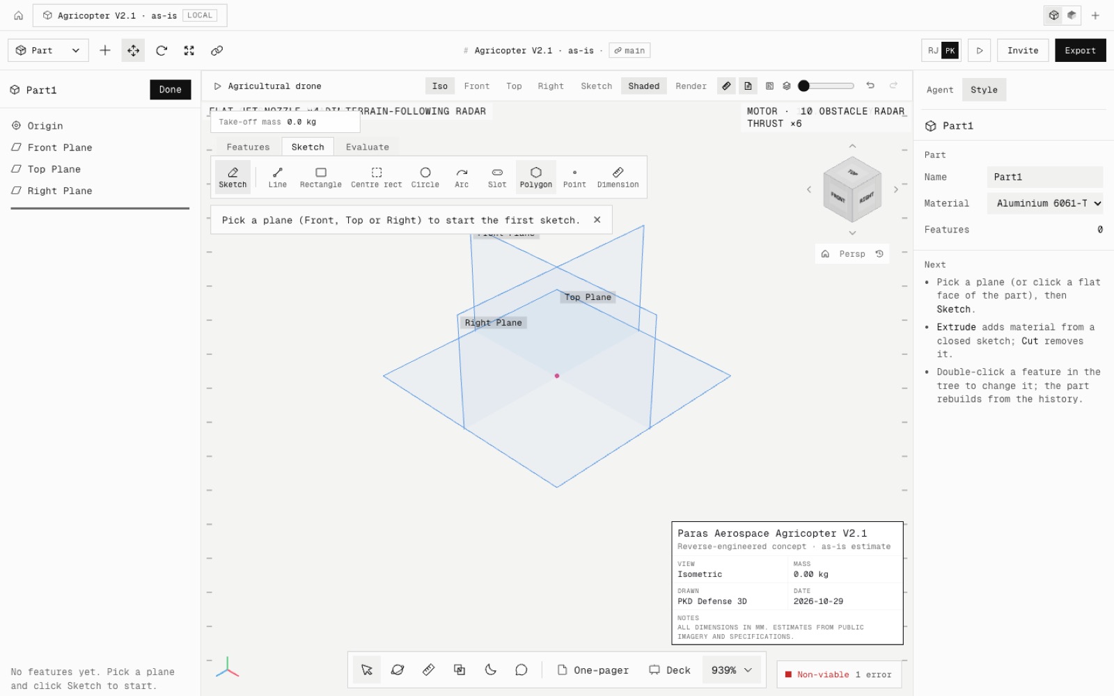
Describe a product in plain English and an agent builds it

Agents connected to Speed now ask a few plain questions, research suppliers and prices, build real curved solids, check the physics and report what is still concept.

After: A plain-English Formula 1 build, before and after real curved solids
Before: A plain-English Formula 1 build, before and after real curved solids
BeforeAfter
The same sentence, before and after

Connect Claude Code or Codex, describe what you want and answer up to four plain questions, each with four choices. The agent then researches the product, records every part with its supplier and price, builds real solids and checks them. Say production and it models every screw and wire.

Every feature now has a short label agents use instead of coordinates, and new tools check a build on the exact solid. Results stay screening grade: nothing here certifies a design.

Added
  • Sourcing with supplier, price and link, and a cost report
  • Ground vehicle physics
  • Curved solid recipes: lofted bodies, airfoil wings, turned parts, tubes and shaped plates
  • Readiness gate, including production level
  • PDF reports of 1, 3, 5 or 10 pages
  • GLB export for Blender and STEP for SolidWorks
  • DXF import and Defeature for agents
Improved
  • Finer curved surfaces when you zoom in
  • No element overlaps text across the app, with an automated check
Fixed
  • Valid solids reported as open at hole seams
  • Parts inside hollow bodies reported as collisions
  • A picture and a drawing requested together failing
Shipped in
ac2b905
Improvementv2.85

More ways to sign in to Speed

Google and Apple have their own sign-in buttons, alongside email links and access codes.

The sign-in screen keeps each choice on a separate row. If a provider is temporarily unavailable, you stay on the form and can choose another method. Google activation is still awaiting the provider credential; Apple opens its account sign-in page, with a complete account sign-in still to be verified.

Your workspace and project settings now recognize signed-in accounts without incorrectly labeling every account as Apple. Existing project permissions and invitation rules remain in place. Return links stay on Speed, including the connection link from an AI chat.

Added
  • Continue with Google alongside Continue with Apple
  • Clear recovery when a sign-in provider is unavailable
Fixed
  • Incorrect Apple labels on email and other signed-in accounts
  • Unsafe return paths containing control characters
  • Malformed sign-in requests now return a clear error
Shipped in
6470a01
Improvementv2.84

A shared command guide for CAD agents

Named colour groups, command discovery and a reusable plan make the same workflows available in Docs and plugins.

The agent guide explains all eight command colour groups alongside explicit availability labels. A colour identifies a category, not a completed feature or an engineering verdict. Existing command codes remain stable even when their category changes.

Agents can read one Markdown workflow, discover typed commands, record prerequisites and checks, validate a batch and recover from partial execution. The full command index is available as JSON. The same guide ships in the updated plugin and is linked from the connector's startup instructions.

Added
  • Named colour legend and full downloadable command index
  • Agent Markdown workflow with planning and batch examples
  • Consistency checks across Docs, plugin instructions and the live command registry
Shipped in
276993d
Featurev2.83

Speed CAD plugins for Claude and Codex

Install the Speed connection and three focused CAD workflows as one plugin package.

The connect, build and screen skills use the existing hosted MCP connector. They discover stable command codes, validate bounded batches and preserve incomplete structural assessments. The plugin does not add a separate geometry backend or a Python runtime.

Download a standalone plugin or a local marketplace bundle from Docs → Plugins. Each client must complete its own authentication and open the paired Speed tab. Local installer validation is separate from a public directory listing or verified connections in every client.

Added
  • Claude and Codex plugin manifests and local marketplace packages
  • Three reusable skills for connection, modeling and structural screening
  • Versioned downloads with checksums and installation instructions
Shipped in
1828c7f
Improvementv2.82

Faster calculations for larger structural models

Structural screening uses a faster calculation path while preserving numerical behavior and the existing engineering warnings.

The calculation kernels were compared bit for bit with the previous implementation. The existing JavaScript path remains available when the faster path cannot run.

Large regression runs now release intermediate model data when it is no longer needed. Performance checks keep the same time limits and record repeated measurements when background machine load affects a run. Results remain screening grade.

Improved
  • Numerical calculations for larger structural models
  • Memory use during the full product regression
Shipped in
113f4d8
Fixv2.81

Clearer structural screening when stress cannot be assessed

Structural results now identify rigid load paths and name the parts whose stress was not calculated. An incomplete load path never becomes a pass or an infinite safety factor.

The report, Simulation panel and agent explain the same limits. A part fixed at every node is listed separately; a plate supported only vertically can still carry stress. Joint-rocking frequencies are identified from their modal energy, including when a frequency band is specified.

Automatic gimbal shock cases now let the base plate deform. Existing results are invalidated by the updated calculation version. Thin-wall models keep their calculated stress; all results remain screening grade.

Fixed
  • Rigid housing stress and safety-factor reporting
  • Whole-plate constraints in automatic gimbal shock cases
  • Cached results from the previous calculation version
  • Stale stress coloring on incomplete load paths
Try it

Run structural screening on a design and read the load-path assessment before using its safety factors.

Open Speed
Shipped in
018258f8b1eaa0
Improvementv2.80

A clearer command reference and a more independent solver

The empty canvas now has an Ask Agent action. Command searches show availability clearly, including tools that are not built yet.

The command reference keeps readable names, color categories and stable codes together. A single search result uses the correct label, and the keyboard reference describes the current Speed appearance.

Report presentation now sits outside the solver modules. Shared geometry and drawing helpers remove three circular dependencies. Detail rendering is checked using an actual evaluated solid at all three detail levels.

Improved
  • Direct Agent access from an empty canvas
  • Clear command availability and theme descriptions
  • Separation of numerical analysis from report presentation
Shipped in
018258f
Featurev2.79

Stable command codes and bounded agent programs

Agents can discover typed Speed commands and send up to 32 steps in one request, using readable operation names or stable short codes.

Settings → Commands → Agent commands lists parameterized, interactive and unavailable entries. The dictionary includes aliases; its size is not a count of implemented features. Codes stay stable when new commands are added.

Programs validate syntax before dispatch, execute sequentially and stop at the first error, cancellation or deadline. Earlier completed changes remain and the receipt says what ran. Each change remains a separate undo step; a program is not an atomic transaction.

The MCP connector still advertises 40 tools. Setup guides distinguish tested connections from documented candidates, exclude Muse, and preserve analysis warnings. Fewer requests do not establish lower token usage or cost.

Added
  • Versioned command codes, schemas and availability
  • Line, vertical-line, rectangle and circle shortcuts
  • Batch validation and partial-completion receipts
  • Client-specific connection guidance
Try it

Open Settings → Commands → Agent commands, or see Docs → Commands.

Open Speed
Shipped in
792fd86
Improvementv2.78

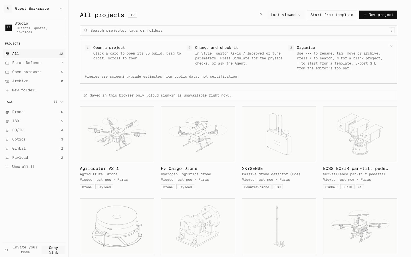
A sharper, simpler Speed website

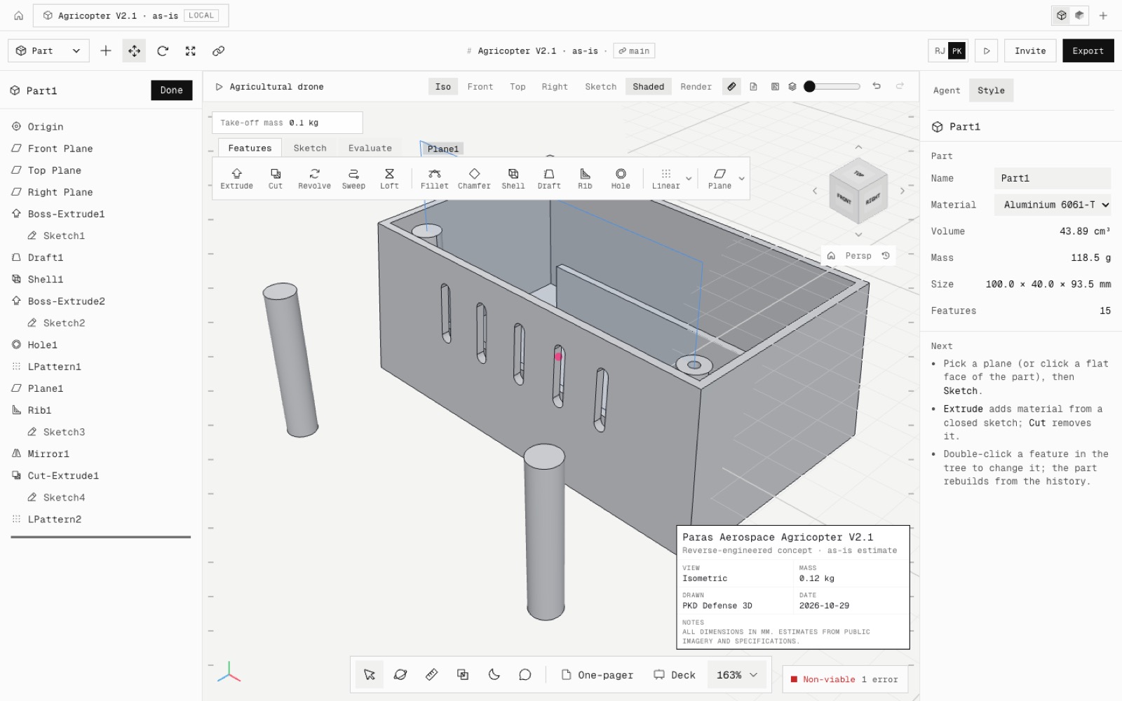
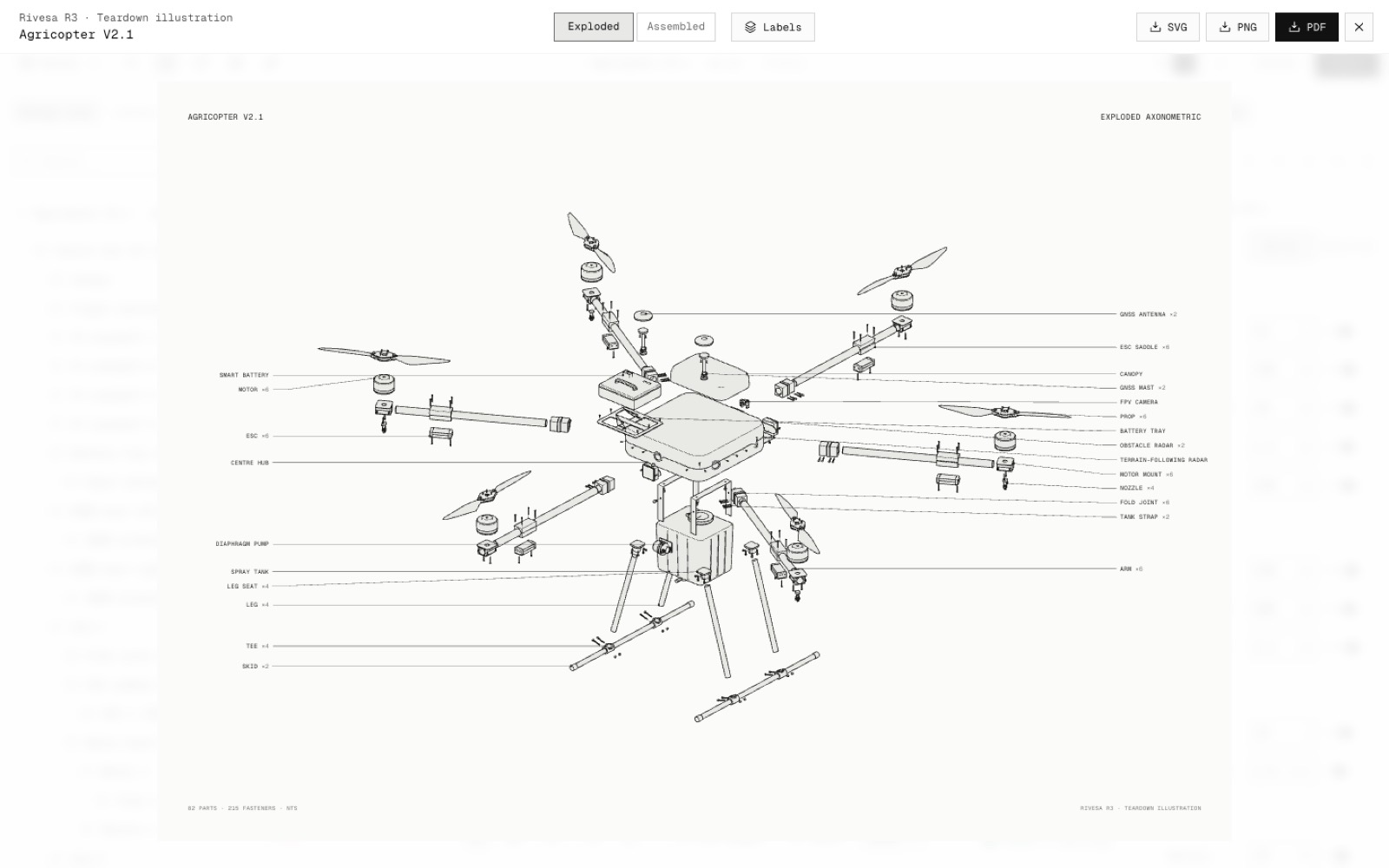
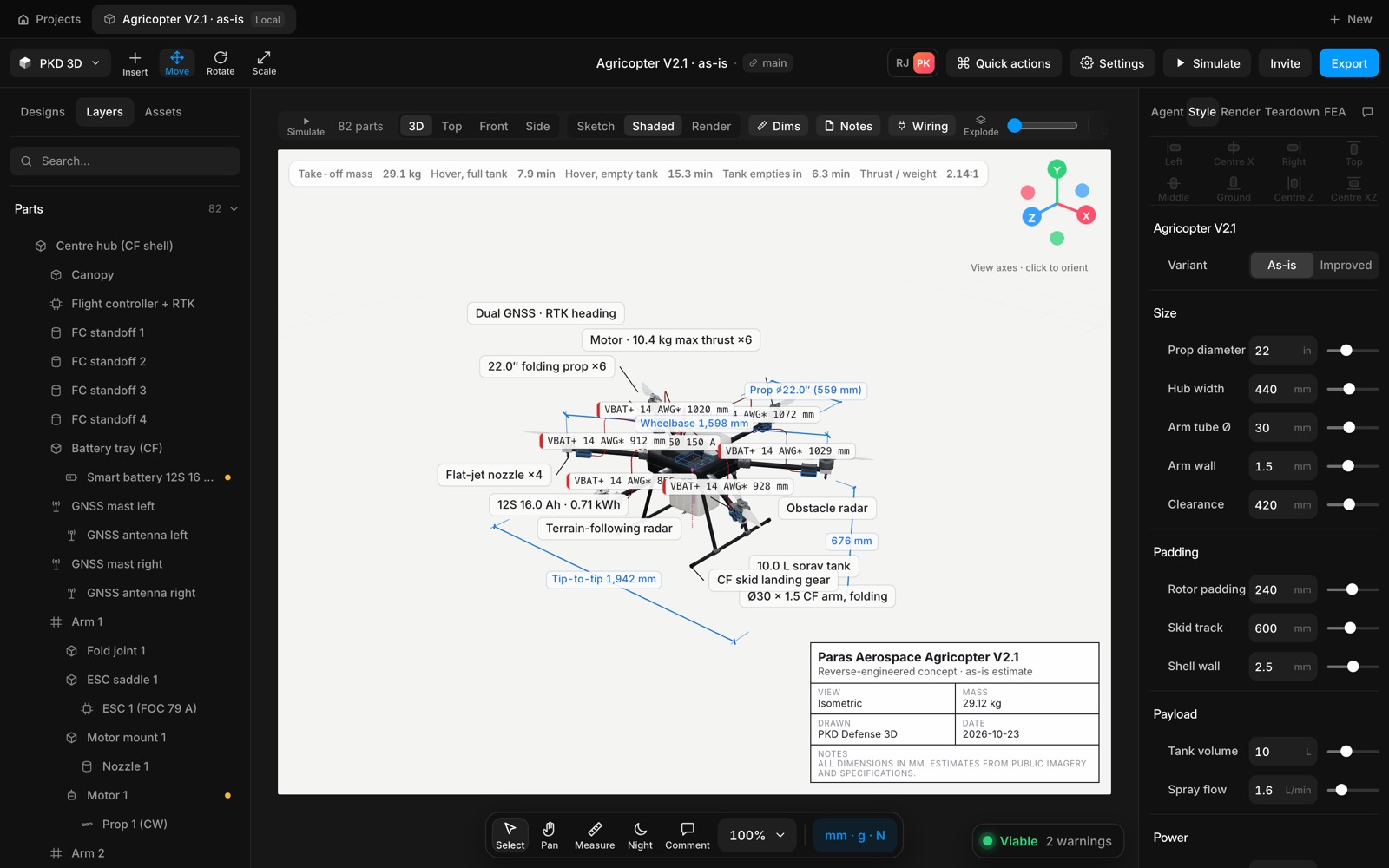
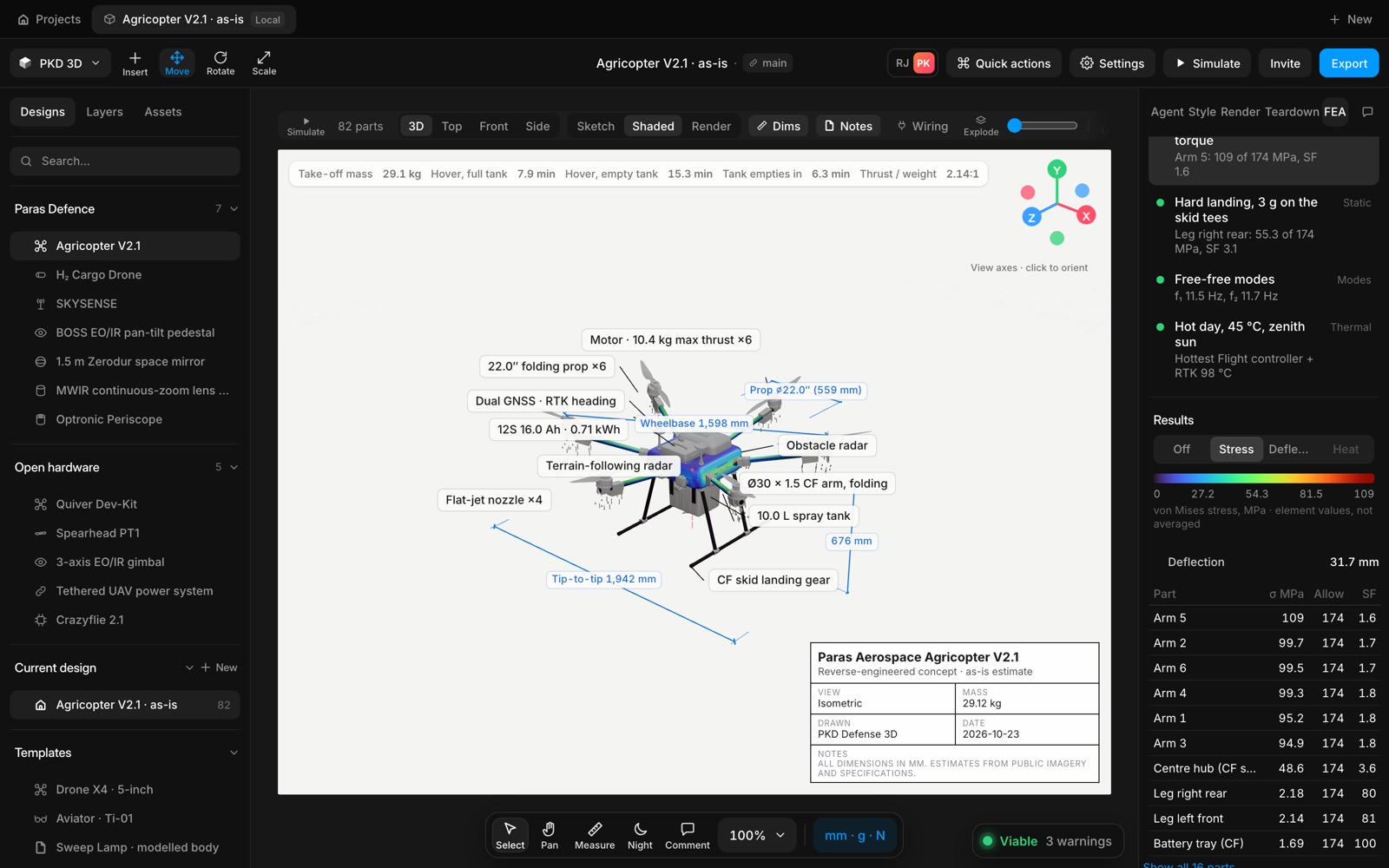
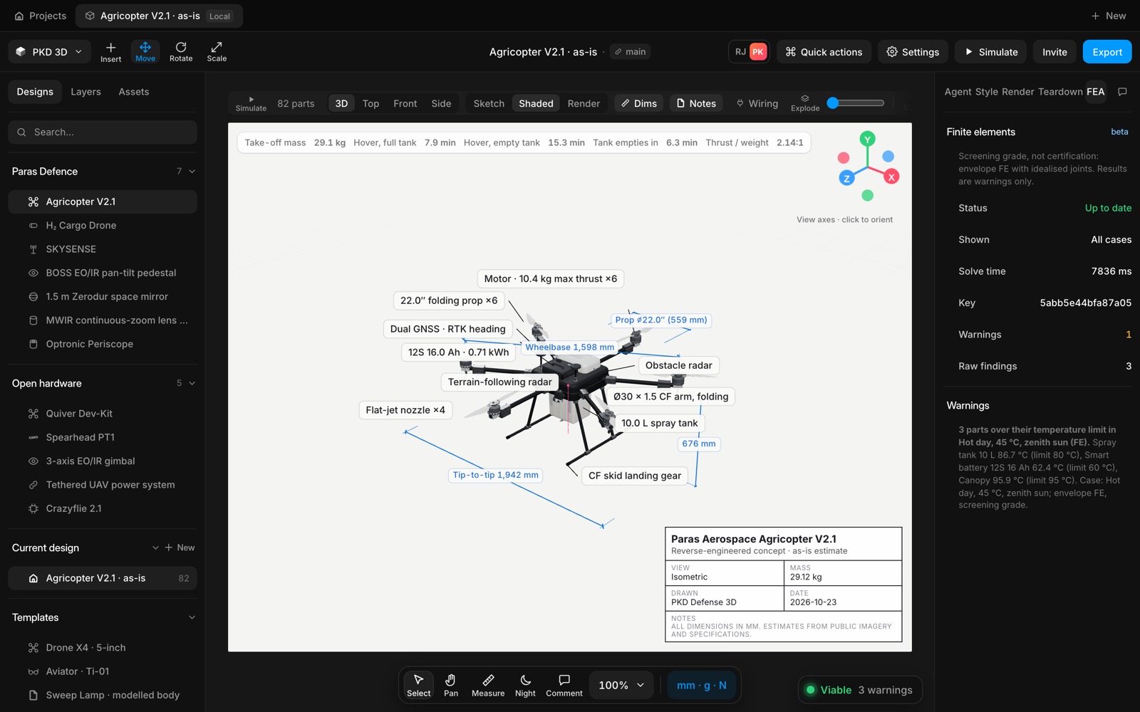
The homepage now has a genuine 82-part agricultural drone preview. Play or pause its exploded view, separate the parts manually, rotate the model, or switch to the top view. Reduced-motion preferences are respected.

The public navigation now keeps Pricing, Docs, MCP and Changelog. The homepage remains, Docs articles remain, and the other marketing routes have been removed. The shared footer is gone.

Switzer typography, a white headline and a continuous black background unify the public pages. MCP client logos retain their colors; new high-resolution drone renders replace the smaller previews. The walkthrough is clearly marked Coming soon.

Improved
  • A sharper, simpler Speed website
Shipped in
cbf37b44139669101d7c9
Featurev2.77

MCP setup and Docs, connected to Speed

The public MCP page explains how an AI chat connects to the open Speed tab, with setup links, a copyable prompt, client compatibility notes and the published tool reference.

Docs includes quickstart, connection instructions, prompts, examples, tools, limits and troubleshooting, with search and machine-readable Markdown endpoints. Client artwork is not a claim of tested support: compatibility notes distinguish tested clients from candidates.

Added
  • MCP setup and Docs, connected to Speed
Shipped in
6372d1f
Improvementv2.76

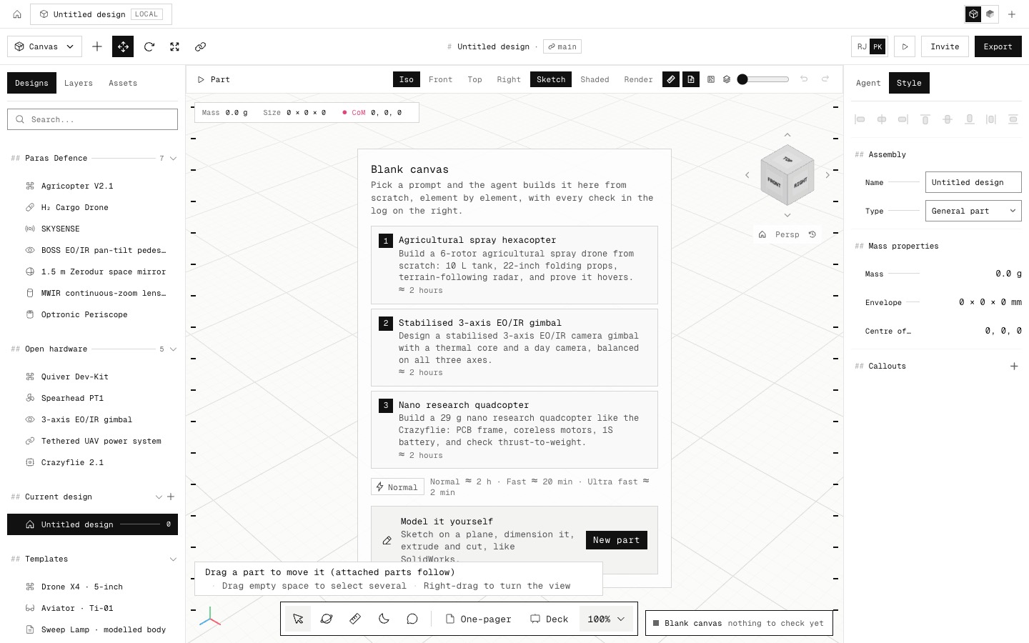
A cleaner workspace, with the same CAD tools

The web editor now uses compact controls, thin dividers, grouped sections and Switzer typography. Design tree, Library and Toolbox stay on the left; Style and Agent stay on the right.

The project settings, dashboard and sign-in presentation follow the same visual system. The original three-chevron Speed mark appears as white strokes on dark surfaces, without a blue tile.

Existing CAD commands remain available. The vertical rail now exposes the shared export actions, while the canvas, agent, saved designs and chat state retain their existing behavior. This release covers the web app; macOS work remains paused.

Improved
  • A cleaner workspace, with the same CAD tools
Shipped in
bfaf68c7e19a4991f654cc87eda116d3711
Fixv2.75

Incomplete stress paths no longer receive a pass

FEA presentation now withholds pass claims for unresolved or rigid load paths. Nonfinite safety factors are described as not computed, including cached summaries.

The safeguard is deliberately conservative and can flag rigid masses that need closer review. It is a reporting safeguard, not a replacement for the pending solver-level repair. All results remain screening grade.

Fixed
  • Incomplete stress paths no longer receive a pass
Shipped in
6118525a763186
Fixv2.74

Hover checks distinguish lift rotors from pushers

Hover thrust, spin, centre-of-mass and arm checks use vertical-axis lift rotors. Current draw and tip speed still account for all motors.

Rotor placement supports positions along level booms. Designs without lift rotors still receive power, tank and structural checks instead of being treated as hover aircraft.

Fixed
  • Hover checks distinguish lift rotors from pushers
Shipped in
8964d3d6b95be4
Featurev2.73

Requirements stay with the conversation

Requirements are attached to the chat rather than stored on the design. The agent can enrich an idea into explicit needs, record checks and combine the final verdict.

Every row is evaluated using its own evidence. Stale or borrowed verdicts are avoided, and user edits are delivered to the agent once.

Added
  • Requirements stay with the conversation
Shipped in
65808e7bfed89c
Featurev2.72

Real solids and a manufacturing pack

A short idea can become a design brief, and a new design starts through a deliberate tool action. Plates, L-brackets, enclosures and flanges can be made as real solids in one call.

The manufacturing pack combines drawings PDF, STEP, a bill of materials and a manufacturability check in one download. Drawings and agent-generated outputs use Speed branding. Review all geometry and engineering assumptions before manufacturing.

Added
  • Real solids and a manufacturing pack
Shipped in
433de529d0f154ccaf6b48e6484c
Improvementv2.71

AI chats work in the intended Speed tab

The connector pairs the browser opened by the chat link and prevents background tabs from taking a build. Switching designs stops the agent; multi-part edits fit the camera to the model.

The browser MCP address explains setup. Status and command discovery guide clients with stale tool lists to newer tools while retaining the 40-tool published interface.

Project lists show the projects you made. Builds can be saved with lettered names, and an empty automatic Part1 is no longer inserted while an AI chat is building.

Improved
  • AI chats work in the intended Speed tab
Shipped in
beb448391b2cbff8a847bd85918f1ec8e0da154b0ab2bcda2c9f9faf5bb4fc006f9d4f
Featurev2.70

Reusable part kits and another aluminium grade

Part kits assemble common drone structures with consistent placement and check behavior. Aluminium 5052-H32 is available in the material library.

Benchmark work recorded both successful workflows and remaining gaps. Historical benchmark verdicts are not a substitute for the current screening limitations or an engineering review.

Added
  • Reusable part kits and another aluminium grade
Shipped in
8c069c4f499783
Improvementv2.69

A simpler sign-in presentation

The sign-in screen presents Apple and work-email options while retaining the access-code gate. The visual presentation follows the compact Speed interface.

Apple provider setup and real-account sign-in validation remain separate owner tasks; this entry does not claim they are complete.

Improved
  • A simpler sign-in presentation
Shipped in
7bc3cc8
Improvementv2.68

PKD 3D is now Speed

The app, its updates page, its reports and its exports now carry the Speed name, the same as tryspeed.ai and the Mac app. The in-app agent runs on Claude Opus 5.5 at medium effort, and only for someone past the access screen.

After: The access screen at 1440 by 900 before, headed PKD 3D, and after, headed Speed
Before: The access screen at 1440 by 900 before, headed PKD 3D, and after, headed Speed
BeforeAfter
Before and after, the access screen at 1440 × 900

Page titles, the access screen, the updates page and its feed, settings, the drawing title block, the FEA report and sheets, and the PDF and DXF exports all say Speed. Designs, links and saved projects are unchanged: only the name people read moved.

The design agent answers on Claude Opus 5.5 with adaptive thinking at medium effort. It runs only for someone who has entered the access code, so the model key can't be used from outside the app.

Pictures on this page are now taken at 2×, so they stay sharp on a Retina screen, and the variant board's 3D draws at full sharpness like the main viewport.

Improved
  • The Speed name across the app, reports and exports
  • The agent on Opus 5.5 at medium effort, behind the access screen
  • Retina pictures on the updates page
Try it

Open the app: the access screen, the title block and the FEA report all say Speed.

Open Speed
Shipped in
d9f5278c4aaef4434c56fbd1152c
Featurev2.67

Compare real parts on every Paras Defence product

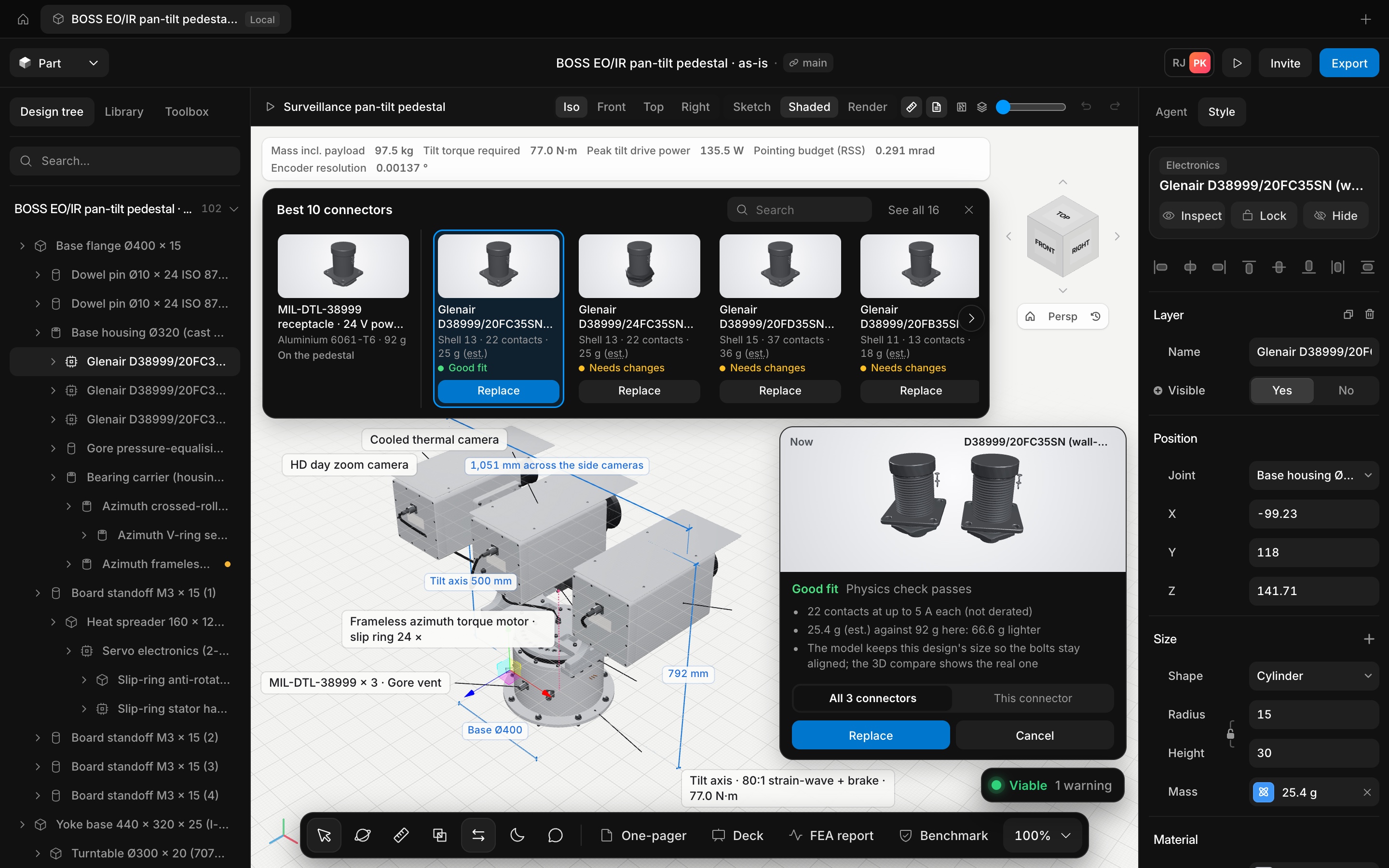
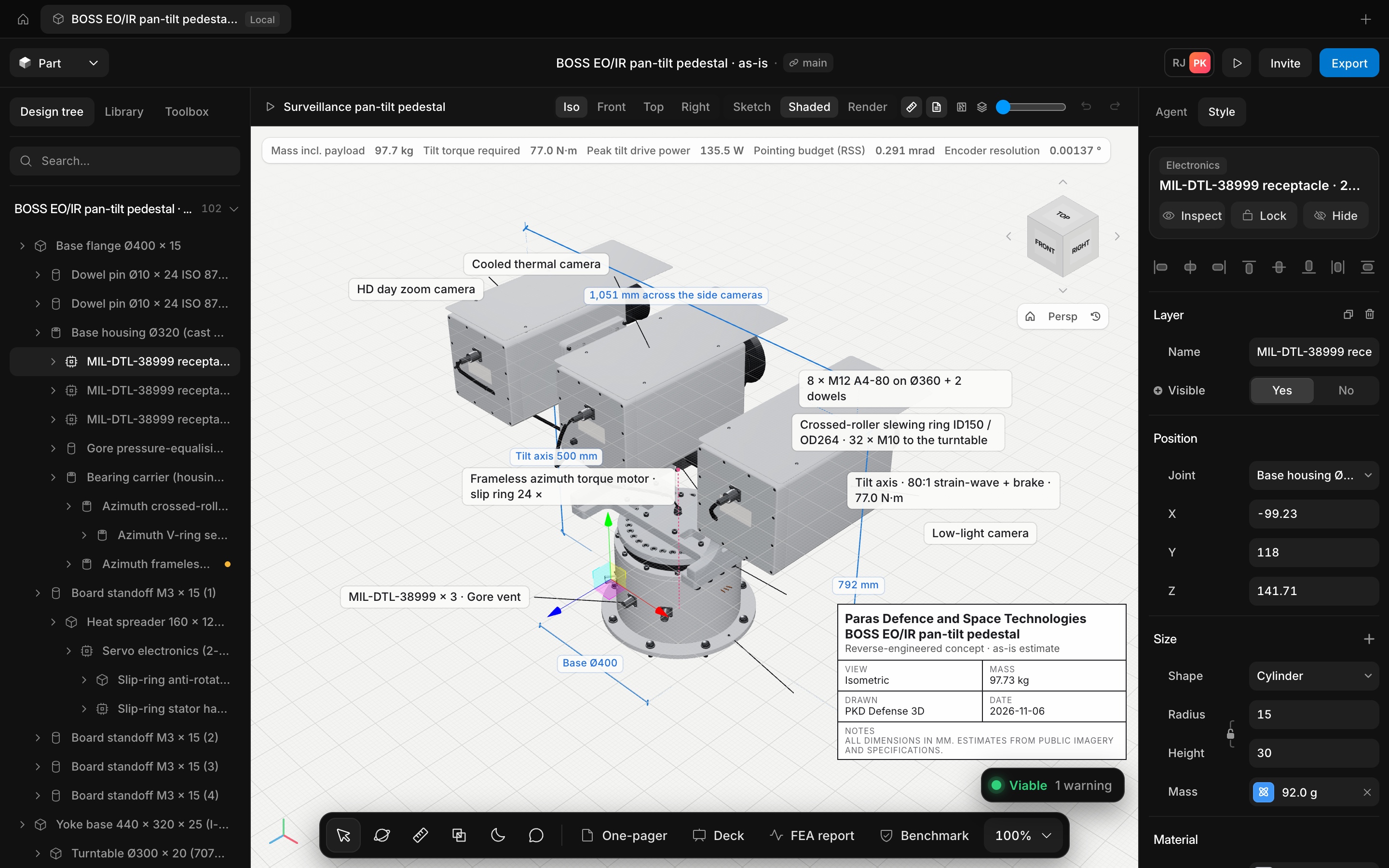
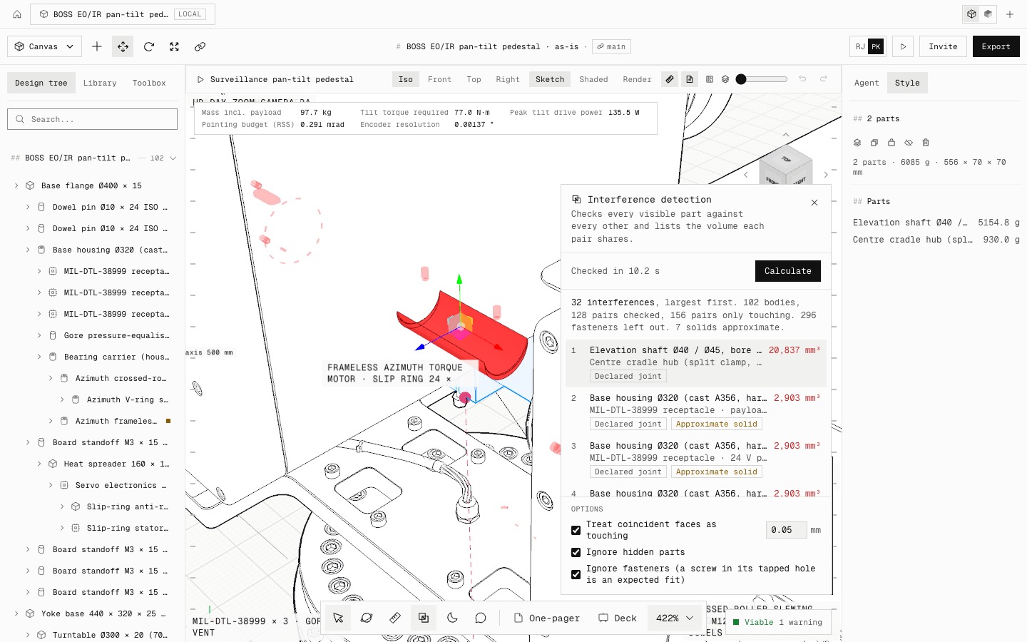
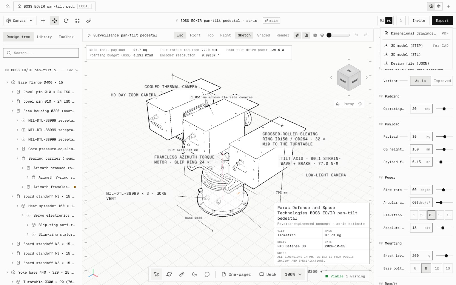
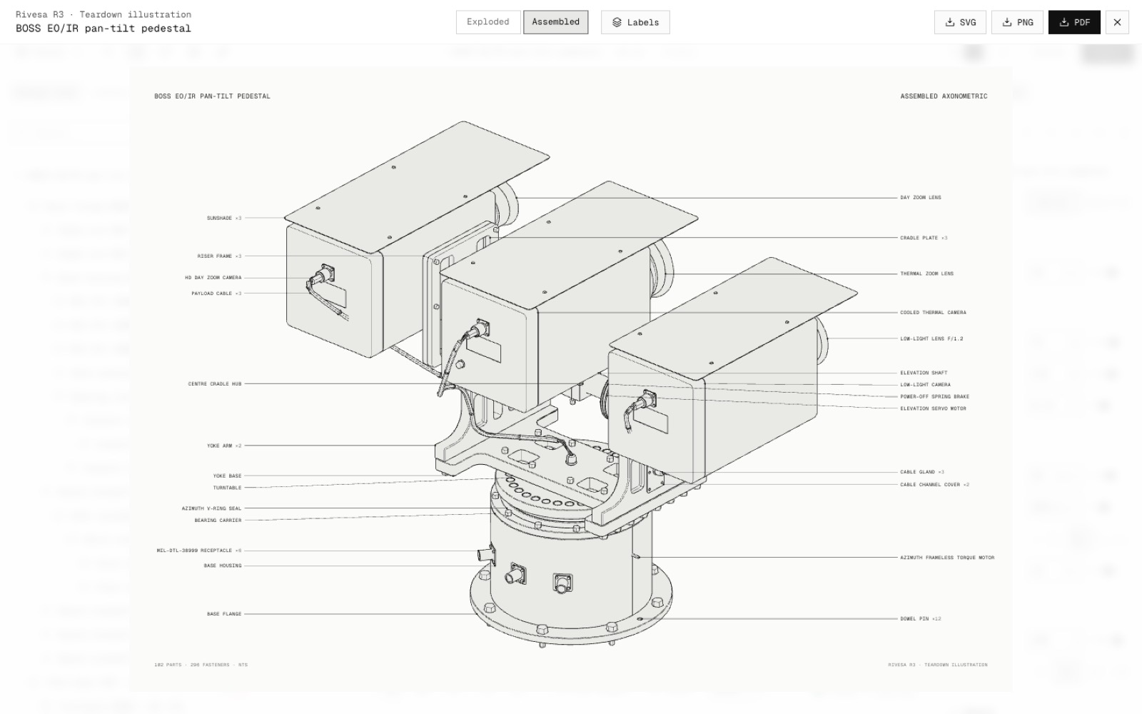
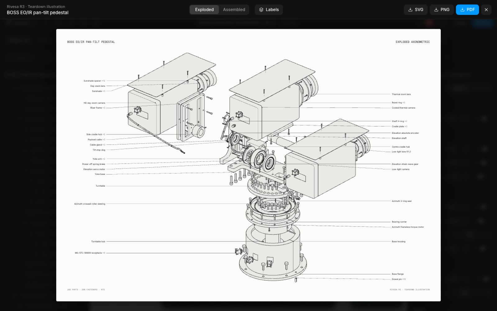
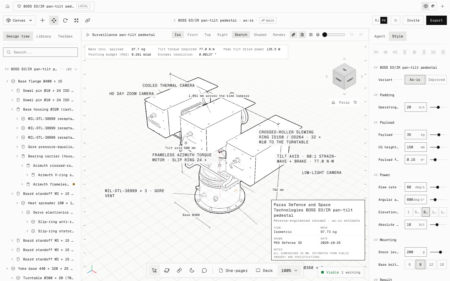
Compare now works on all seven Paras Defence products and on designs you build, not only the Agricopter. Click a connector, a torque motor, a slip ring, an encoder, a thermal core, a lens or a window heater and see real parts from other makers, checked against this design. Replace waits for the physics check, so one click can't break a design that works.

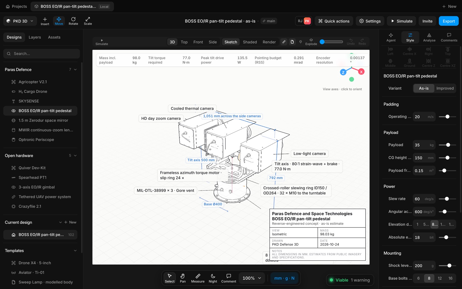
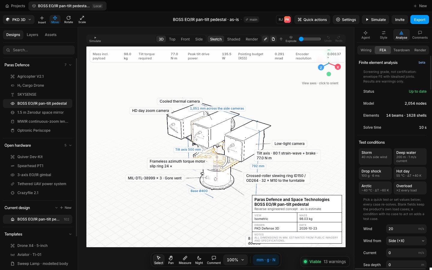
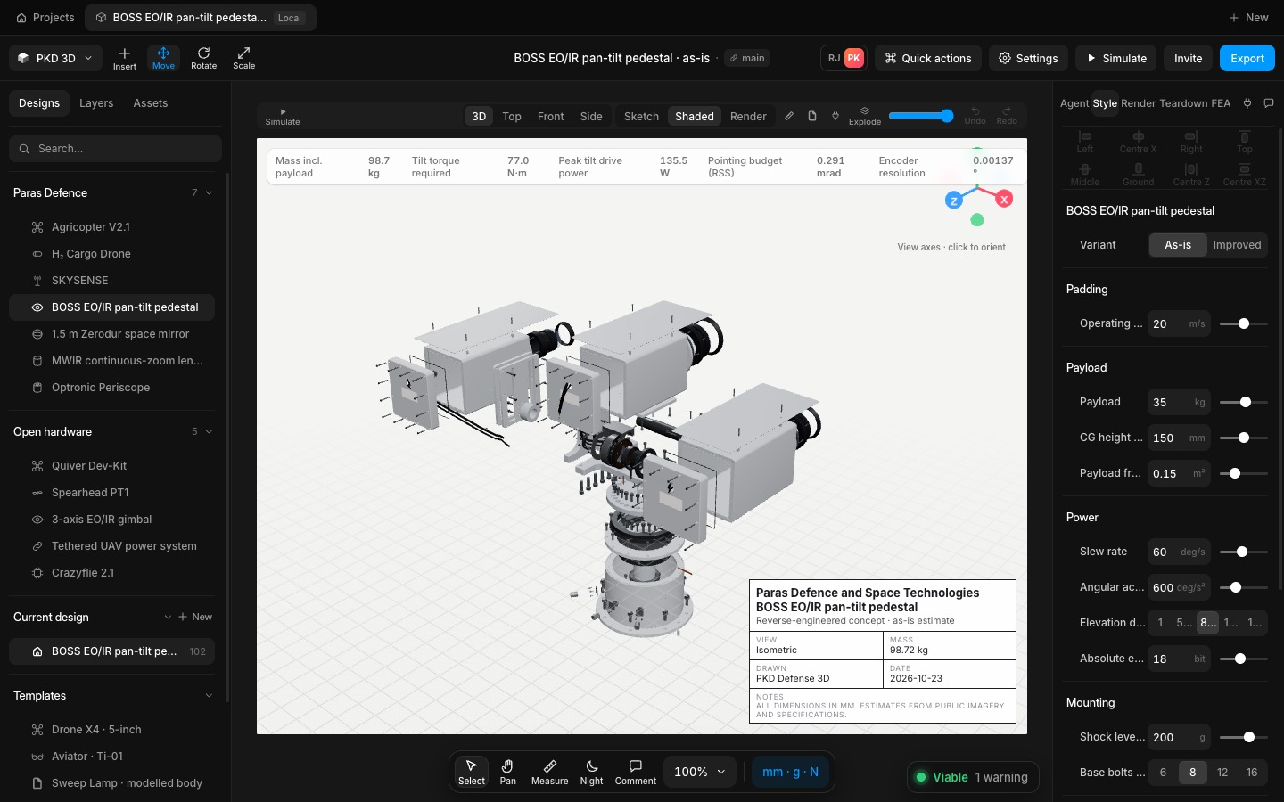
After: The BOSS pedestal at 1440 by 900 before, with Compare unavailable, and after, with real MIL-DTL-38999 connectors across the top and one compared beside the design
Before: The BOSS pedestal at 1440 by 900 before, with Compare unavailable, and after, with real MIL-DTL-38999 connectors across the top and one compared beside the design
BeforeAfter
Before and after, BOSS pedestal at 1440 × 900

110 new sourced catalogue entries cover frameless torque motors and gearmotors, slewing rings and large bearings, encoders, slip rings, MIL-DTL-38999 Series III connectors, cooled and uncooled thermal cores, EO cameras, thermal zoom lenses and window heaters. Every entry cites the maker's own page or a maker-authored datasheet, and every estimated figure is marked est. with a tooltip.

What a part can be compared with now comes from what the part is (its kind, role and size), never from the product. Each kind has its own fit checks: envelope, mass, bore and bolt circle, torque and voltage, shell size and mount, band, pixel pitch and focal length. A missing figure caps the verdict at Needs changes and says which figure is missing.

A part made to the design, such as a housing, a flange or a mirror blank, says so and suggests a bought-in part to click instead. A bought-in kind the catalogue doesn't hold yet, such as a hydrogen cylinder, a seal or a dowel pin, says that plainly. The Agricopter's results are byte-for-byte what they were.

Replace stays off, marked Checking, until the physics check for that option is in, and it refuses an option that would make a passing design fail, saying why. The agent's swap_part uses the same rule, so it never fits a part Compare doesn't list. Undo is read aloud to screen readers, and the figures chip at the top left no longer runs under the view cube or the Compare strip.

Added
  • Compare on all seven Paras Defence products and on your own designs
  • 110 sourced market parts in 11 kinds
  • Fit checks per kind, with Good fit, Needs changes or Won't work
Improved
  • Undo and Redo are announced to screen readers
  • Plain words when nothing in the catalogue matches
Fixed
  • Replace could fit a part that broke a passing design
  • The agent could fit a part onto something Compare calls made to the design
  • Figures chip under the view cube at 1280 and 1440 wide
Try it

Open the BOSS pedestal, press Compare and click one of its connectors.

Open Speed
Shipped in
bd26dad
Fixv2.66

Nothing on the canvas overlaps

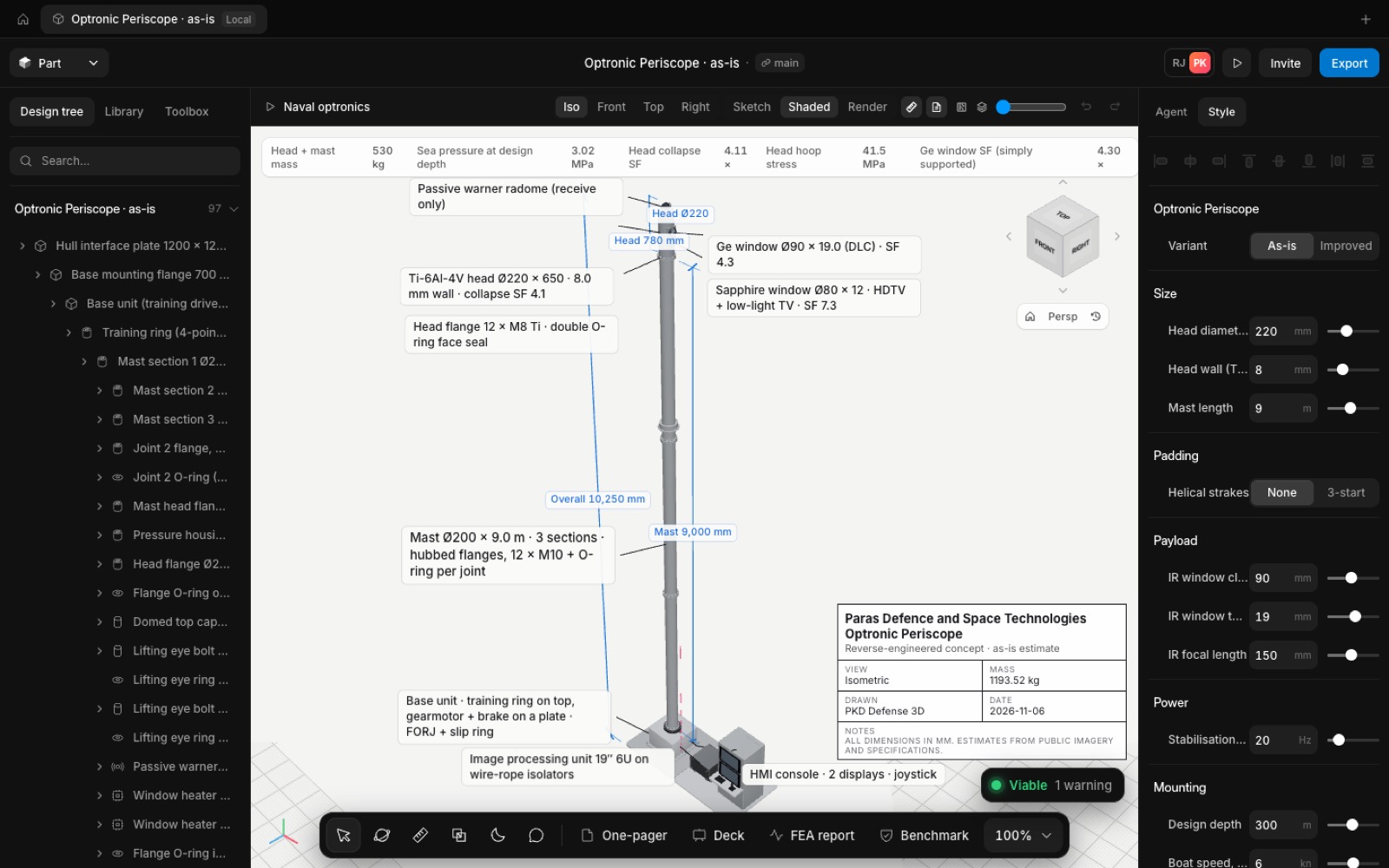
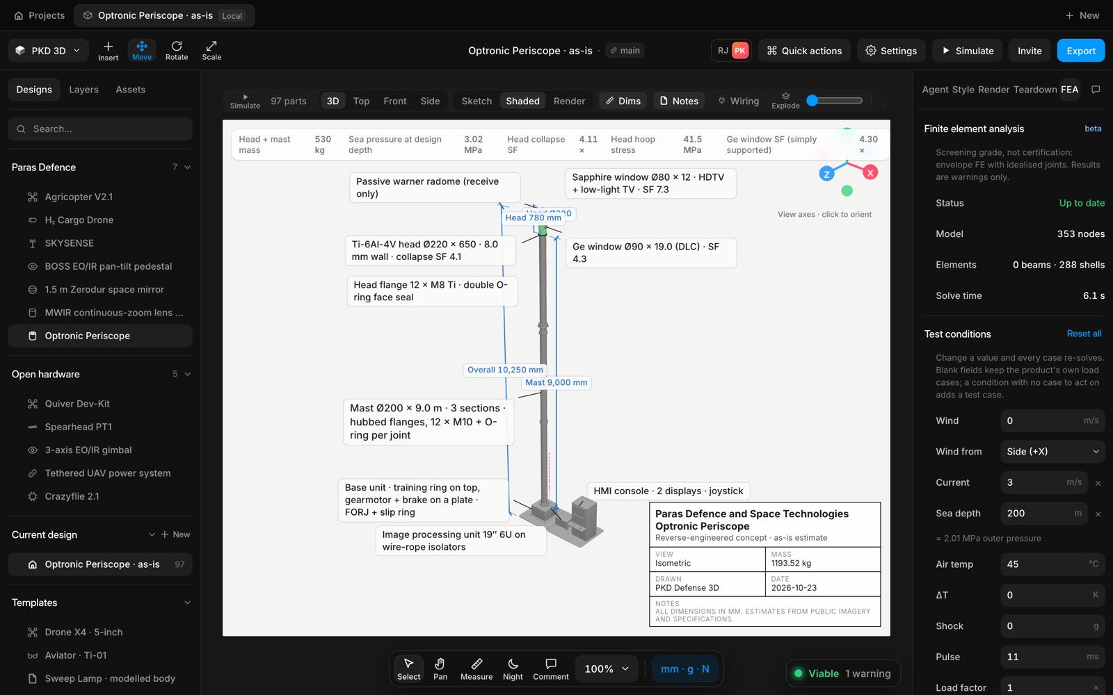
The Viable pill, the zoom menu, dimension values, callouts, the Compare strip and panel and the bottom dock no longer cover each other or get cut off, at 1280, 1440 and 1920 wide, in light and dark. Compare also answers a click faster and keeps keyboard focus in view.

After: The Optronic Periscope at 1440 by 900 before, with the Viable pill under the right panel and two dimension values on top of each other, and after, with both clear
Before: The Optronic Periscope at 1440 by 900 before, with the Viable pill under the right panel and two dimension values on top of each other, and after, with both clear
BeforeAfter
Before and after, Optronic Periscope at 1440 × 900

On a canvas narrower than 1,140 px the Viable pill moves up above the right end of the bottom bar instead of sliding under the right panel, so One-pager, Deck, FEA report and Benchmark keep their words at 1440 wide. The viability card and the zoom menu stay inside the canvas.

Two dimension values that meet in a view now step apart instead of printing over each other (the Periscope's head diameter and head height), and a callout pushed back inside the canvas is checked again where it lands. Checked on all seven Paras Defence products at three sizes: 0 overlaps.

Esc closes the viability card or the zoom menu first and puts focus back where it was, and Tab reaches the card right after its pill. Low-contrast chips, title-block cells and the zoom menu's hover now pass WCAG AA.

In Compare, picking a card answers in about 32 ms in a production build (it was 216 ms), a card reached with the keyboard is always scrolled into view, and Esc or Replace (on the card or in the panel) right after a pick act on what is on screen. Replace, the preview and the agent's swap_part use one rule for what may be fitted, and a swap of mixed parts no longer depends on the order they were listed in.

Improved
  • Esc and Tab on the viability card and zoom menu
  • WCAG AA contrast on chips, title block and menus
Fixed
  • Viable pill and zoom menu under the right panel
  • Dimension values printed over each other
  • A callout pushed onto a dimension when kept inside the canvas
  • Compare option click took over 200 ms
  • Esc right after a Compare pick closed Compare instead of the panel
  • Mixed-part swaps depended on list order
Try it

Open the Optronic Periscope at 1440 wide and look at the head dimensions and the Viable pill.

Open Speed
Shipped in
b1bf33151955e4
Featurev2.65

Compare with real parts, FEA report and Benchmark test

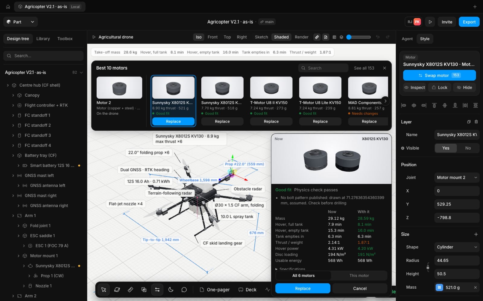
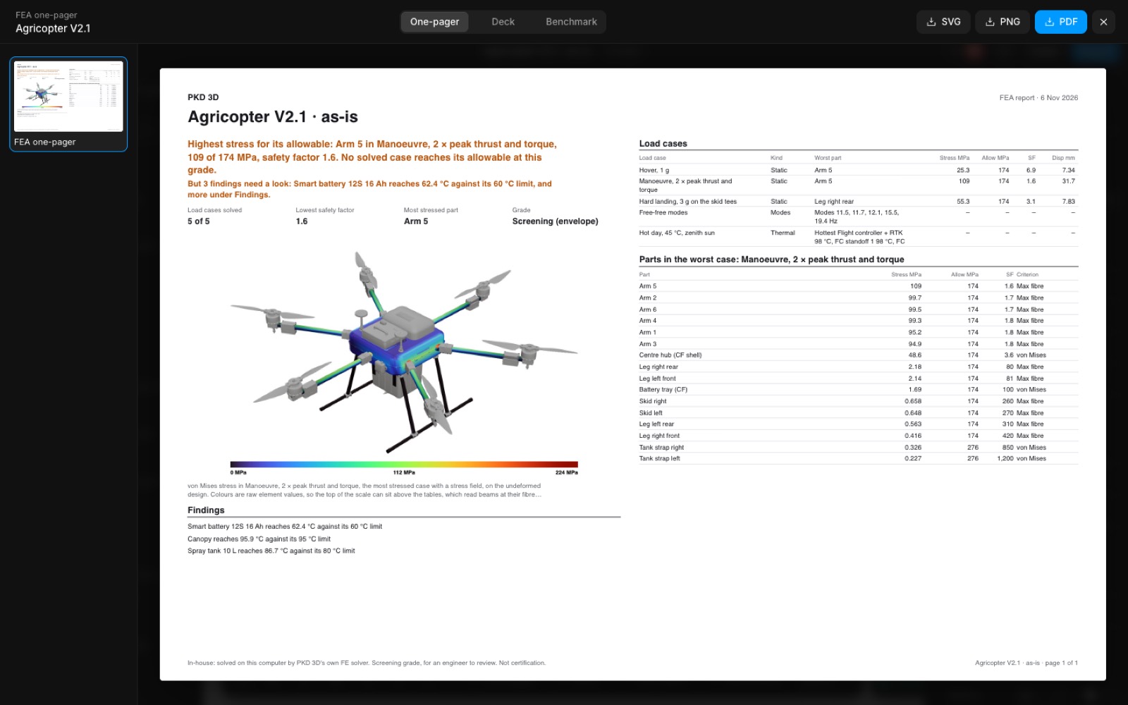
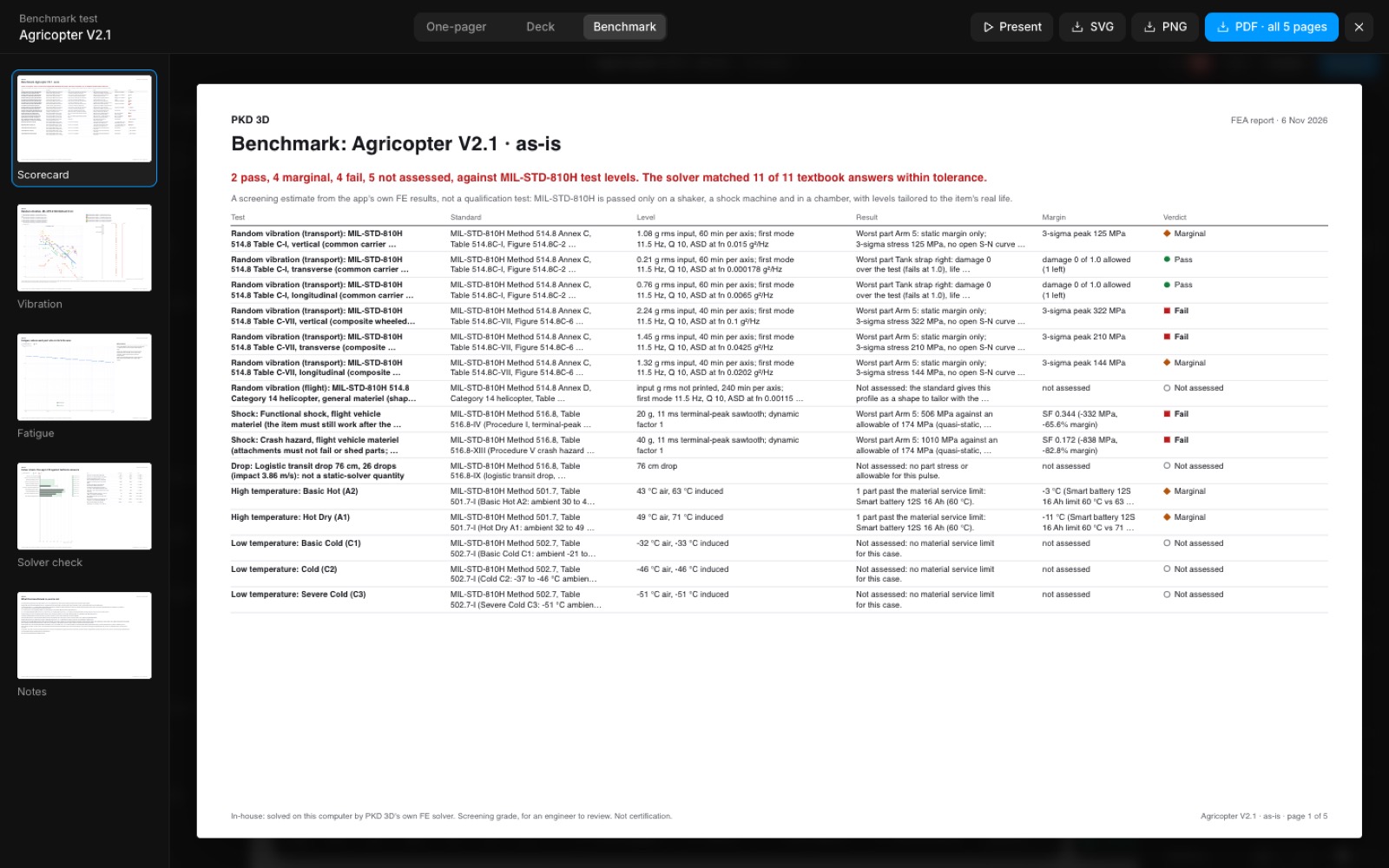
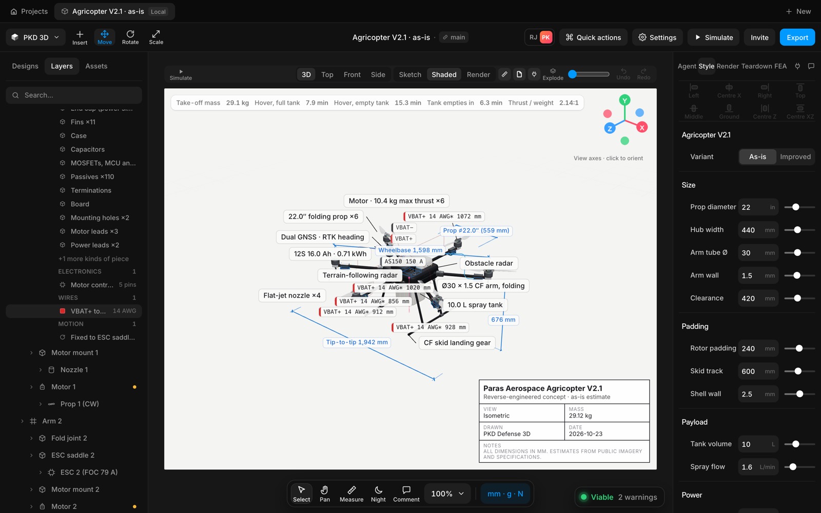
On the Agricopter V2.1, click any part, or any screw after Split up, and press Compare: the 10 best real industry parts slide across the top, each checked against this drone. Pick one to see it beside yours in 3D with the flight figures now and with it, then Replace it on this part or all of them. The FEA report and the new Benchmark test print as a one-pager, a deck or a PDF, solved on this computer.

After: The Agricopter before, then with the best 10 motors across the top and the side-by-side panel open
Before: The Agricopter before, then with the best 10 motors across the top and the side-by-side panel open
BeforeAfter
The canvas before, and Compare on a motor
The FEA one-pager for the Agricopter
FEA report, one-pager
The Benchmark scorecard against MIL-STD-810H levels
Benchmark scorecard

Compare is in the bottom bar and in the part's right-click menu. The strip shows the part on the drone, then the best 10 from about 1,000 sourced catalogue entries. Each card has a 3D picture, one line of key figures and a plain verdict: Good fit, Needs changes or Won't work. Slide it with the arrows, the mouse wheel or a drag, or search all of them.

All 153 propulsion motors from 7 makers fit with their real can size, height, mass, thrust and KV. They draw in the sketch, the drawings and the render. The motor mount and prop screws move to the motor's own pattern, and an assumed pattern says so. A motor that pulls more than the battery can supply, or takes a different cell count, is marked as needing changes or as won't work.

Picking a card previews it on the drone with no undo step. Replace fits it as one undo step, on this part or all matching parts, and the figures on the canvas update. Swaps survive slider changes and saving.

FEA report solves every load case with the app's own FE solver and prints a one-pager or a deck. Benchmark screens the design against MIL-STD-810H random vibration (Miles' equation, Steinberg three-band fatigue with Miner's rule), shock and temperature levels, with S-N and PSD charts. It also checks the solver against 11 closed-form cases. It is screening grade, for an engineer to review, and not certification.

Added
  • Compare with real parts on the Agricopter V2.1, for any part or screw
  • 1,001-entry sourced parts catalogue, including 153 propulsion motors
  • FEA report: one-pager, deck and PDF
  • Benchmark test: MIL-STD-810H vibration, shock and temperature screen, plus 11 solver checks
Try it

Open the Agricopter V2.1, click a motor, then press Compare in the bottom bar.

Open Speed
Shipped in
1320aa6
Improvementv2.64

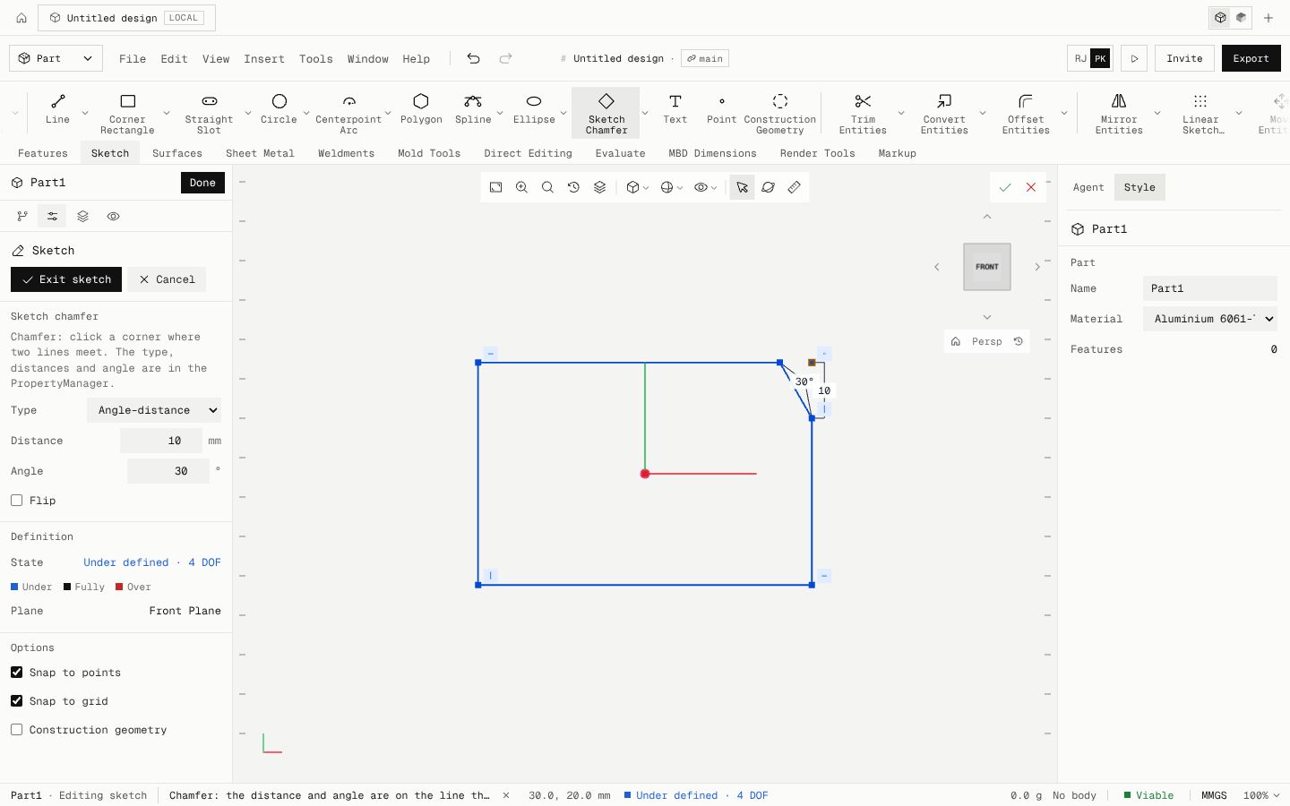
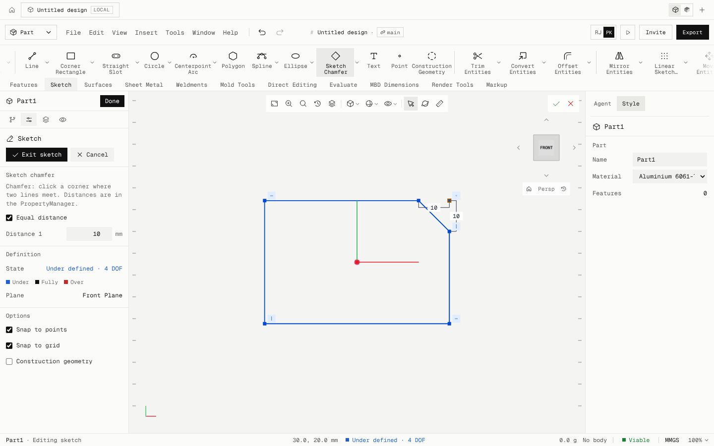
Sketch Chamfer: Angle–distance

Sketch Chamfer now has an Angle–distance type: a distance along the first line and an angle from it, held by a distance and an angle dimension. Editing the angle keeps the value you type, past 90° too.

After: A rectangle corner chamfered with equal distances, then 10 mm at 30° with the Angle–distance type
Before: A rectangle corner chamfered with equal distances, then 10 mm at 30° with the Angle–distance type
BeforeAfter
Equal distance (before) and Angle–distance

Pick Angle–distance in the Chamfer PropertyManager, type the distance and the angle, then click the corner. Flip puts the distance and angle on the corner's other line. Distance–distance and Equal distance work as before.

The sketch solver now holds the chamfer's angle as a directed angle, so editing it from 30° to 100° on a 56.3° corner gives the cut-back the law of sines says (9.804 mm) instead of quietly solving to the supplementary 80°.

The chamfer line is construction geometry exactly when the corner's first line is. Checked against closed form on 90°, 123.7° and 56.3° corners. Core parity is now 162 of 239.

Added
  • Sketch Chamfer Angle–distance type
Fixed
  • A sketch chamfer's angle dimension no longer solves to its supplement when edited across 90°
Shipped in
80809b6
Fixv2.63

Building by hand on the full toolset: nine parts, assemblies and frames, and two fixes

The hand-building test now drives the SolidWorks-style ribbon and builds ten designs through the real screen: the motor mount plate, flanged shaft, enclosure, duct and handle, an edit session, a sheet metal bracket, a surface model, a welded frame, a gearbox assembly and a drawing. Two problems it found are fixed: a new mate could flip a part upside down, and a double-click on Exit sketch or Cancel could also hit what sat behind it.

The motor mount plate built by hand on the new ribbon
Motor mount plate
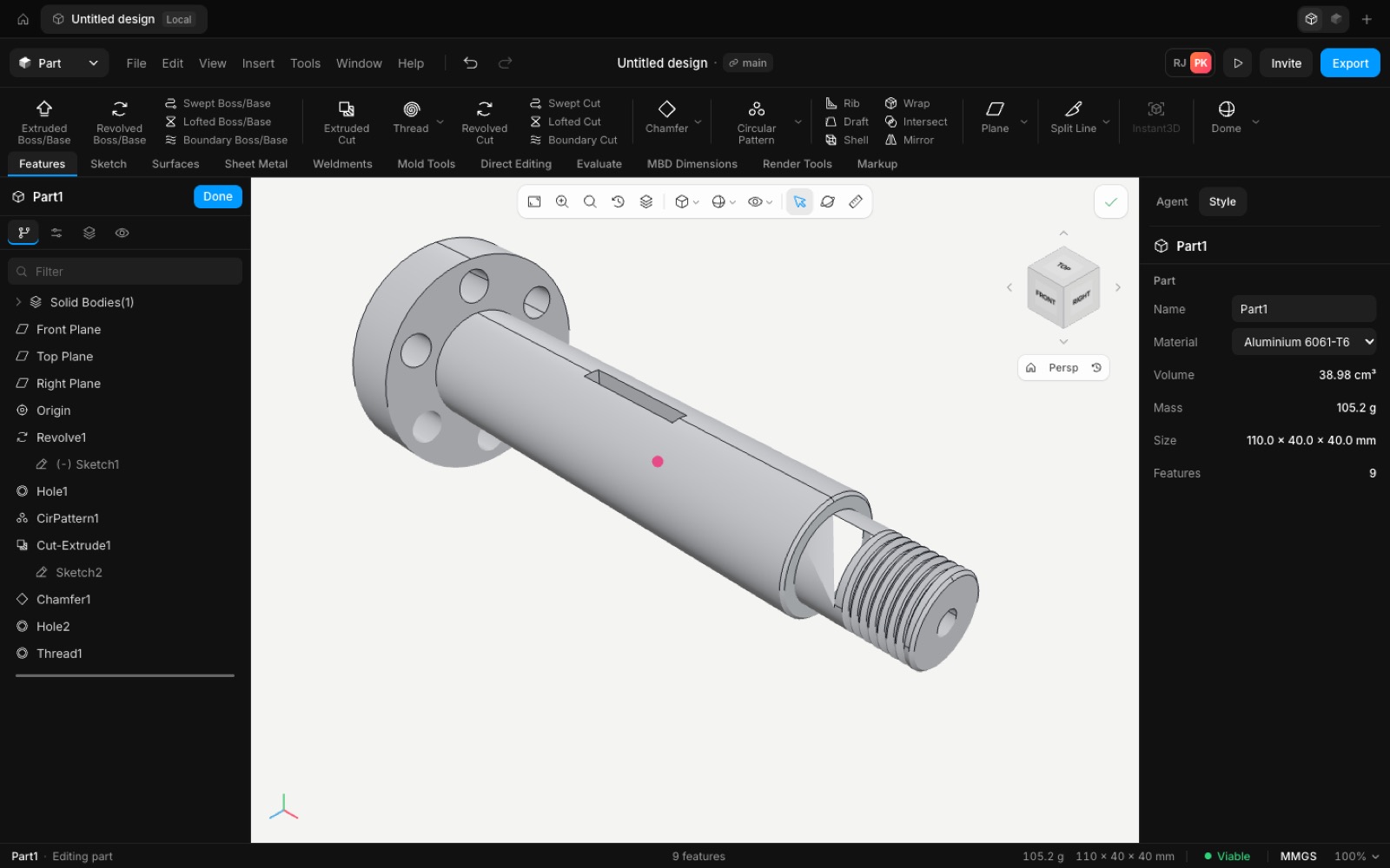
The flanged shaft: centerline, ⌀ dimensions, revolve, circular pattern, keyway, thread
Flanged shaft
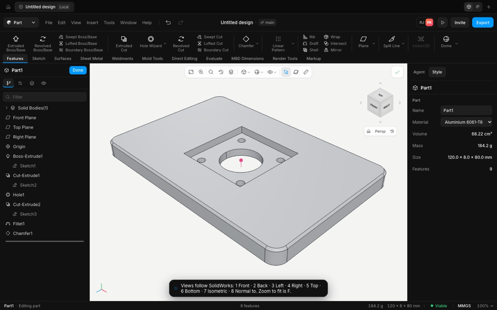
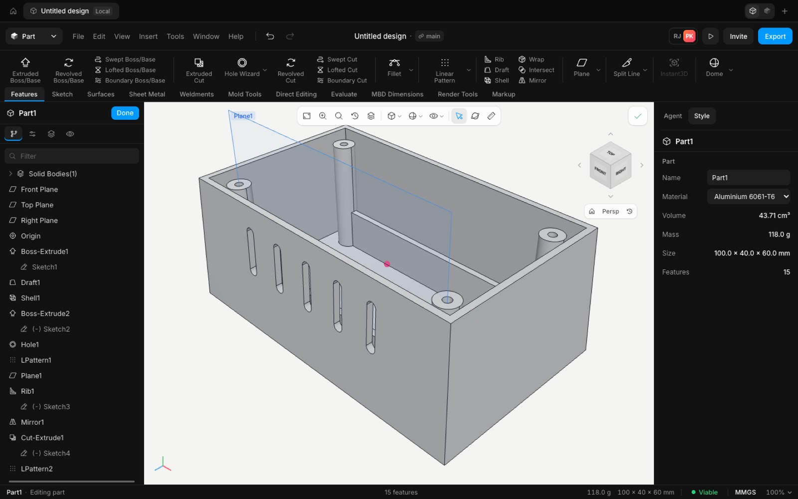
The electronics enclosure, 100 × 60 × 40, every boss inside
Electronics enclosure
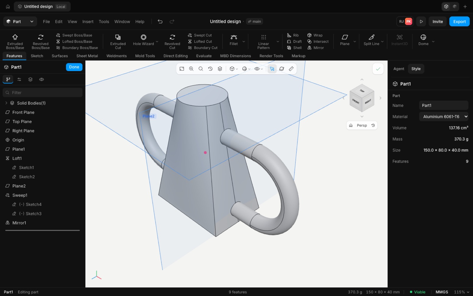
The lofted duct with swept handles
Duct and handle
Build 1 after edits: thickness changed, rollback, suppress, delete, rename
Edits and robustness
A sheet metal U channel with a hem, flattened
Sheet metal bracket
A lofted surface trimmed, knit and thickened 2 mm
Surface model
A welded square-tube frame with its cut list
Welded frame
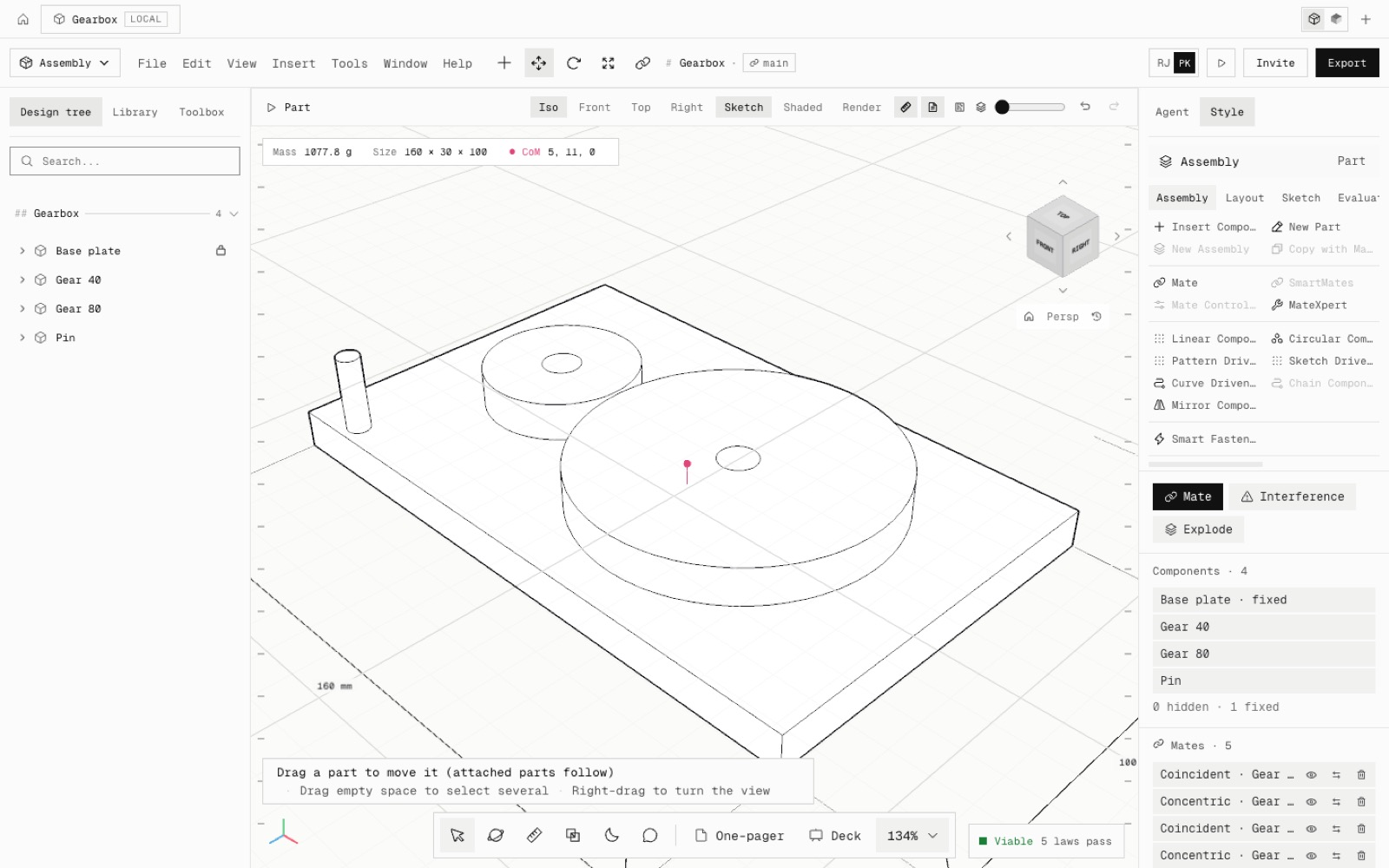
A gearbox assembly with a gear mate, four patterned pins and its bill of materials
Gearbox assembly

A new mate now starts with the alignment nearest to where the parts already are, so mating a gear to the base plate leaves it upright instead of flipping it.

Exit sketch and Cancel ignore the second click of a double-click, which used to land on the canvas or the next panel.

The test finds each button by its command id rather than its position, so it keeps working as the layout changes, and it can run the whole set several times in a row. The screenshots are the dark theme, taken at the end of each build.

Improved
  • The hand-building test drives the new ribbon and covers sheet metal, surfaces, weldments, assemblies and drawings
Fixed
  • A new mate could flip a part (it now keeps the nearest alignment)
  • A double-click on Exit sketch or Cancel also clicked through
Shipped in
8e6ae34
Improvementv2.62

The agent runs live on GPT-6.1 Terra

The in-app agent now runs on OpenAI's GPT-6.1 Terra with the project's own key. GPT-6 models go through OpenAI's Responses API, the only one that takes tools with reasoning for them, so the agent reasons about the design while it calls the modelling commands.

Tested live from one sentence: "an aluminium mounting bracket, an 80 × 40 mm plate, 20 mm thick, with R2 fillets on the four vertical corner edges and four M6 clearance holes, 60 by 24 mm apart, centred". The agent planned, sketched, extruded, drilled four M6 clearance holes, filleted the four edges and ran the physics check in 81 seconds. The part it built is exactly the closed-form volume, 61,194.37 mm³, the same as the one built by hand.

Older OpenAI models keep the Chat Completions path. OPENAI_MODEL picks the model and OPENAI_API_STYLE can force either path.

Improved
  • Agent on GPT-6.1 Terra (Responses API, medium reasoning)
Shipped in
b083b40
Improvementv2.61

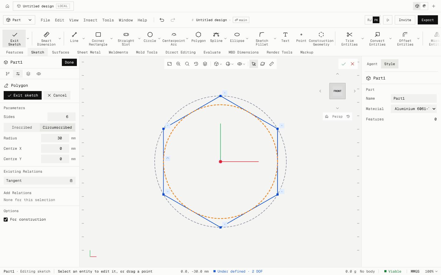
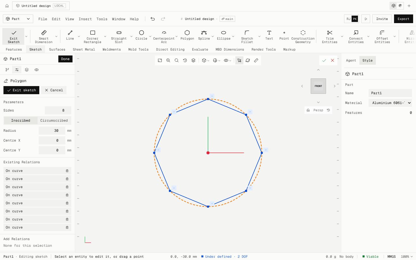
Polygon: Inscribed or Circumscribed

The Polygon sketch tool now has an Inscribed or Circumscribed choice. Circumscribed draws the polygon around its circle, so the radius you type is the distance across flats ÷ 2, as for a hex nut.

After: An inscribed octagon, then a circumscribed hexagon with its incircle
Before: An inscribed octagon, then a circumscribed hexagon with its incircle
BeforeAfter
Inscribed (the old behaviour) and Circumscribed

Inscribed works as before: every vertex sits on the construction circle. Circumscribed keeps an incircle tangent to every side at its midpoint, so a hexagon with radius 30 measures 60 mm across flats.

The relations keep the polygon regular as you drag it (a square stays square, not a rhombus) with the same degrees of freedom as before. Changing Sides keeps the mode, and every edit is one undo step. The agent can draw a circumscribed polygon too.

Checked against closed form: a circumscribed hexagon with apothem r has area 2√3·r², and extruded 10 mm at r = 20 it builds to 13 856.4 mm³. Core parity is now 161 of 239.

Added
  • Polygon Circumscribed option
Shipped in
7598397
Featurev2.60

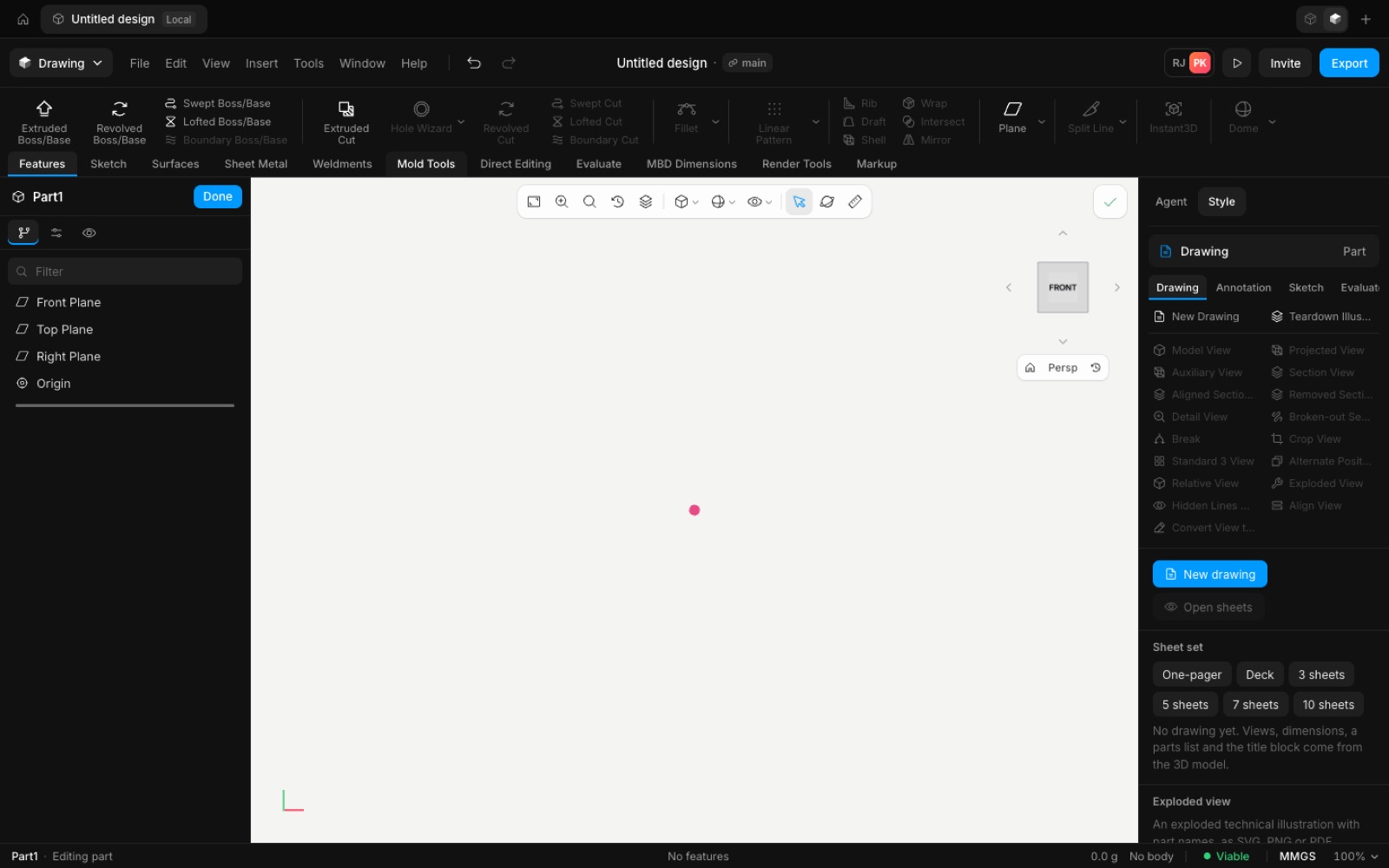
Assemblies by hand: advanced and mechanical mates, component patterns, exploded views and a BOM

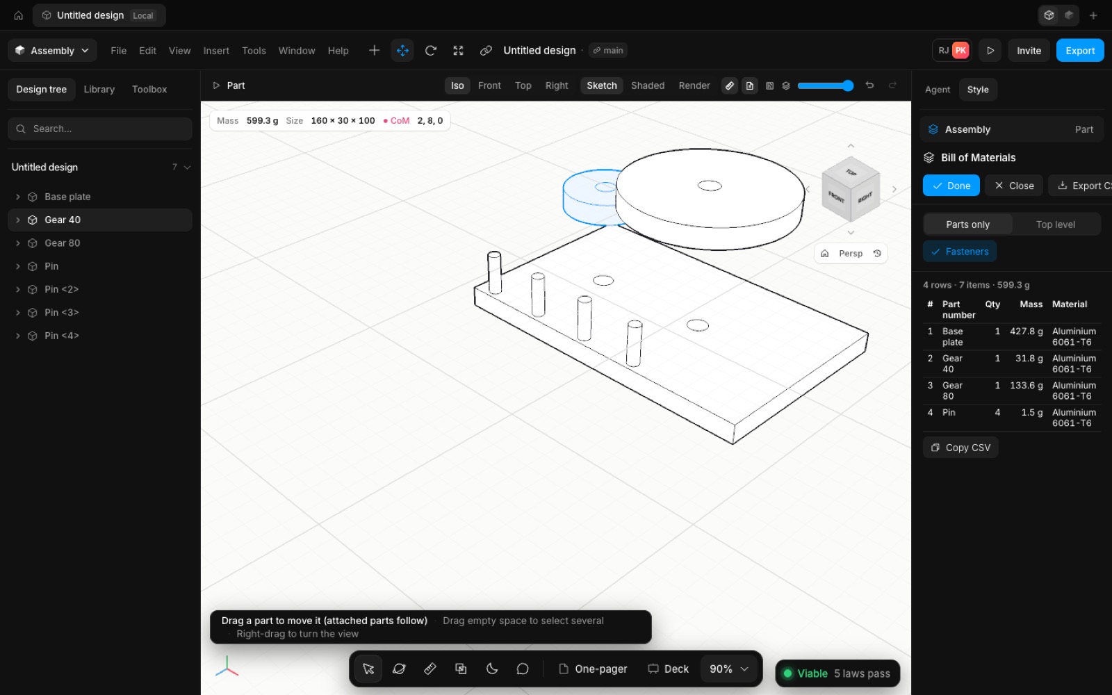
The Assembly tab is built out. Insert Components places a part, a new part or a STEP file by clicking. The Mate panel has Standard, Advanced and Mechanical tabs: tangent, lock, width, symmetric, limit, path, linear coupler, profile centre, gear, rack and pinion, screw, cam, hinge, slot and universal joint. Component patterns (linear, circular, pattern-, sketch- and curve-driven) and Mirror Components, exploded views with explode lines, a bill of materials, Smart Fasteners, hole series and assembly cuts complete it.

After: The Assembly workspace before and after, with the Assembly tab's commands lit
Before: The Assembly workspace before and after, with the Assembly tab's commands lit
BeforeAfter
The Assembly tab
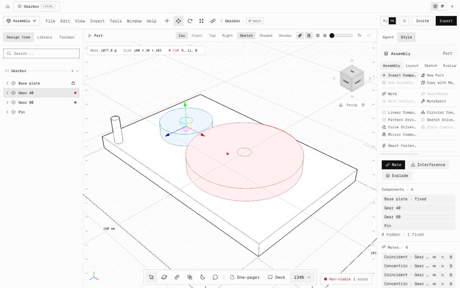
A gearbox with a gear mate: gear 1 turned 40°, gear 2 follows to −20°
Gear mate
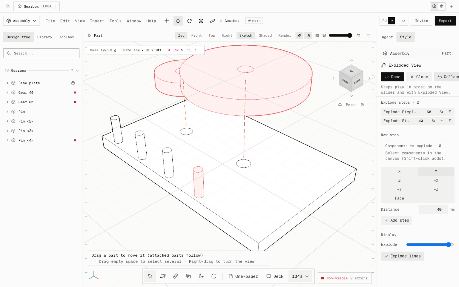
The gearbox exploded in two steps with explode lines
Exploded view
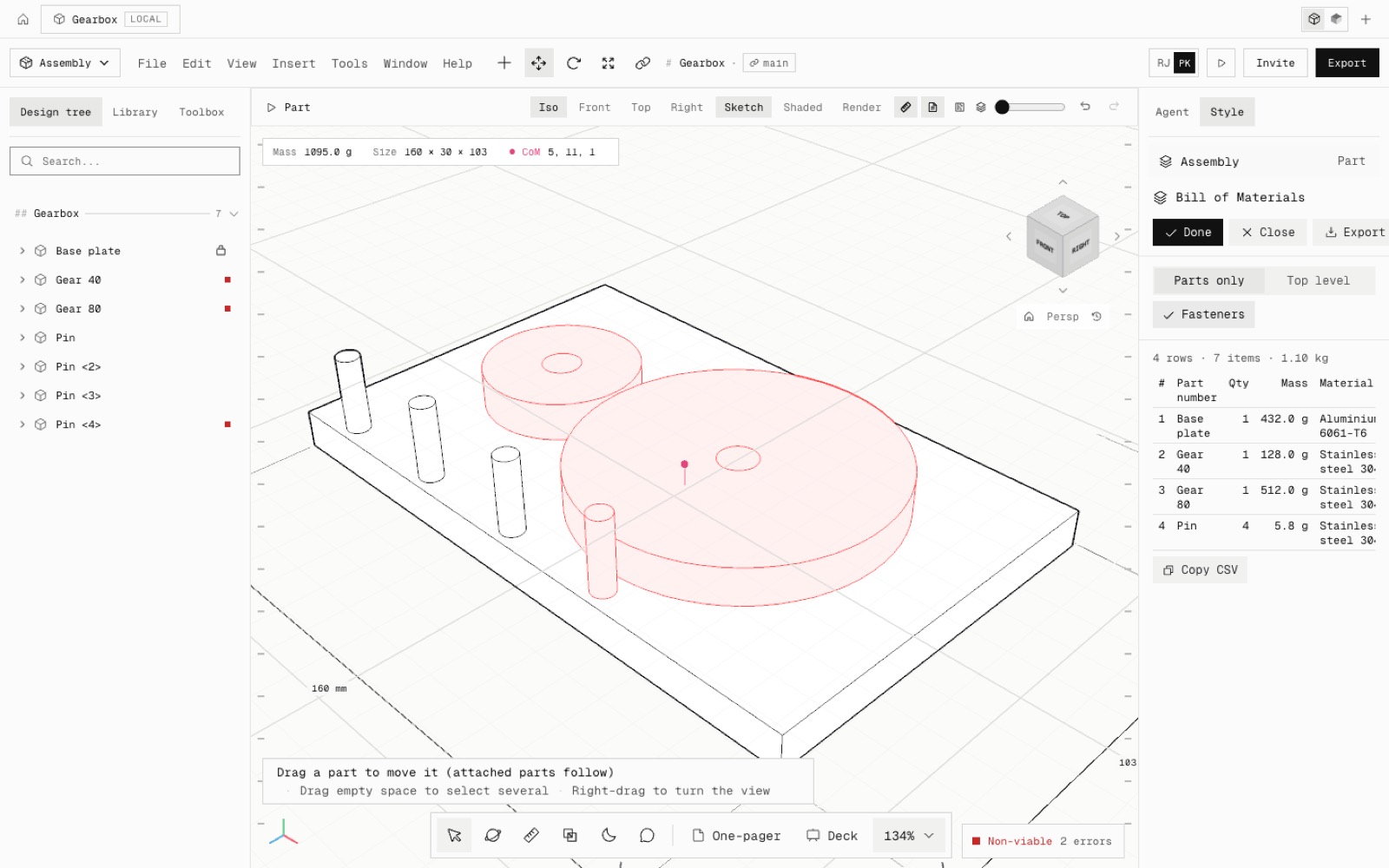
The bill of materials with quantities
Bill of materials

Mates drive the parts through one solver that counts each component's degrees of freedom. A 20 : 40 gear mate turns the second gear −20° when the first turns 40°, a rack travels r·θ, a screw advances its lead per turn, and a limit mate clamps the distance to its range. The Mates folder lets you edit, suppress, flip and delete mates.

Tested by hand in the app: a small gearbox (base plate, two gears, a pin). The gear mate was picked by clicking both gears, and Move Component turned gear 1 by 40° and gear 2 followed to −20°. Interference Detection found no clash, a linear pattern made four pins, the exploded view has two steps with explode lines, and the BOM lists the pins as 4.

Assembly cuts and hole series cut through every part they cross, and Smart Fasteners fills matching bores with ISO bolts. Every command is one undo step the agent can also make.

Not yet: chain pattern, SmartMates, Mate Controller, physical dynamics, belts and chains, flexible subassemblies, forces in motion studies, and live-drag clearance. Core parity is now 160 of 239.

Added
  • Insert Components
  • Advanced and mechanical mates, MateXpert
  • Component patterns and Mirror Components
  • Exploded views with explode lines
  • Bill of materials
  • Smart Fasteners, hole series, assembly cuts
  • Collision detection, clearance and hole alignment checks
  • npm run test:assembly2
Shipped in
e41b9fb
Featurev2.59

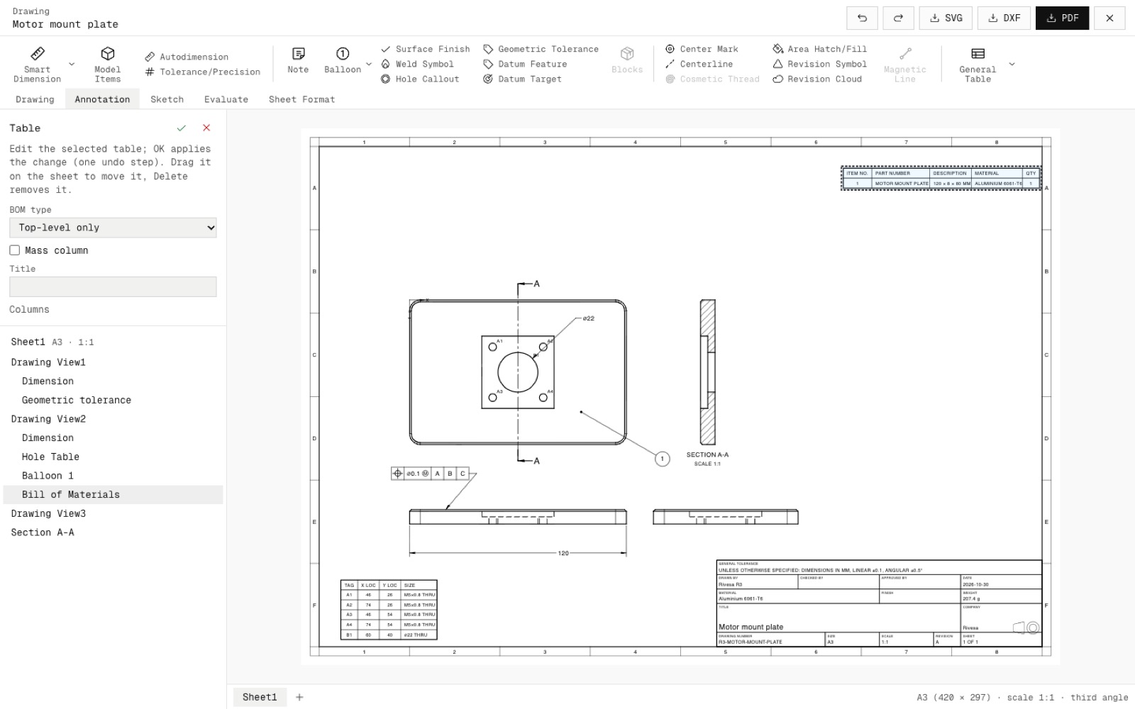
Drawings by hand: views, dimensions, GD&T, balloons, hole tables and a BOM

Drawing workspace → New drawing by hand opens a sheet editor with SolidWorks' Drawing, Annotation and Sheet Format commands: 47 in all. Place model, standard 3 view, projected, auxiliary, section, detail, broken-out, break and crop views. Dimension them (smart, diameter, angular, chamfer, ordinate, baseline, chain). Annotate with notes, balloons, surface finish, weld symbols, hole callouts, GD&T frames, datums, centre marks and hatches, and add hole tables, a BOM and a revision table.

After: The Drawing workspace before (generated drawings only) and after (the motor mount plate drawn by hand: views, section, dimensions, hole table, GD&T, balloon and BOM)
Before: The Drawing workspace before (generated drawings only) and after (the motor mount plate drawn by hand: views, section, dimensions, hole table, GD&T, balloon and BOM)
BeforeAfter
A drawing made by hand
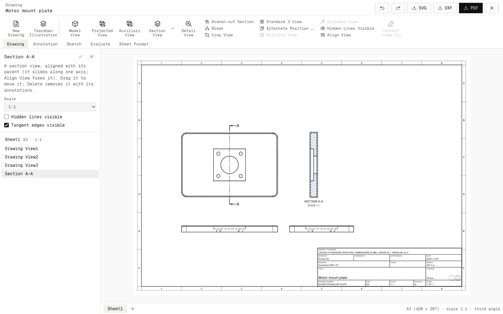
Section A-A placed by picking, its cut faces hatched
Section view
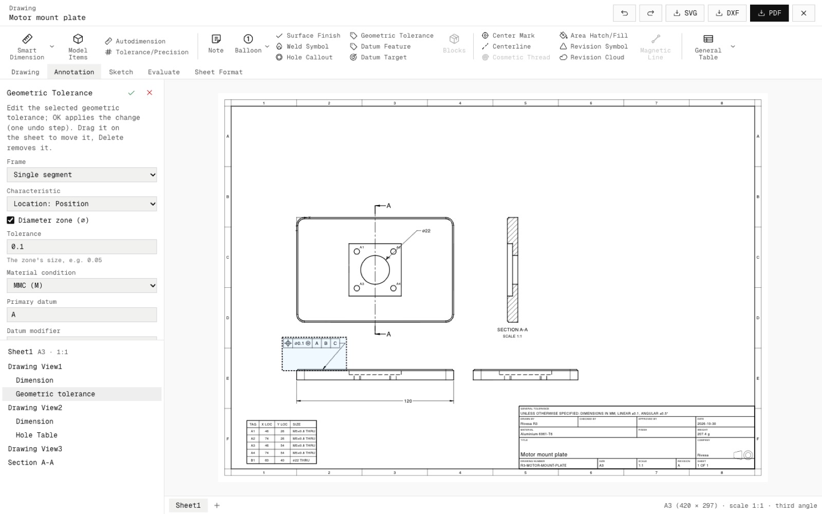
A geometric tolerance frame and datum on the sheet
GD&T

Every view comes from the exact solid and every dimension is driven by it. The motor mount plate reads 120, ⌀22, R6 and 1 × 45°, and when the plate is made 140 wide the dimension follows. Projected views stay aligned with their parent and move with it, and an auxiliary view shows an inclined face at its true size.

The editor has the ribbon across the top, a PropertyManager and the drawing tree on the left, the sheet in the middle and sheet tabs below. The next item previews as you place it, and you can select, drag and delete. Every command is one undo step, and the drawing saves with the design.

Title block fields link to the part's custom properties. Drawings export to PDF, SVG and DXF at true scale: a 120 mm edge prints 340.157 pt at the drawing's scale.

Tested by hand in the app: the motor mount plate's drawing, with a front view, top and right projections, Section A-A, dimensions, a hole table, a GD&T frame, a balloon and a BOM, exported three ways.

Not yet: half, offset and aligned sections, Relative View, blocks, weld and bend tables, and drawings saving in projects made from a product's sliders. Core parity is now 141 of 239.

Added
  • Sheet editor: New drawing by hand
  • 47 drawing, annotation and sheet format commands
  • Hole table, BOM and revision table
  • Title block linked to custom properties
  • npm run test:drawing-editor
Shipped in
1c07bf7
Featurev2.58

Evaluate tab, equations, configurations and design tables

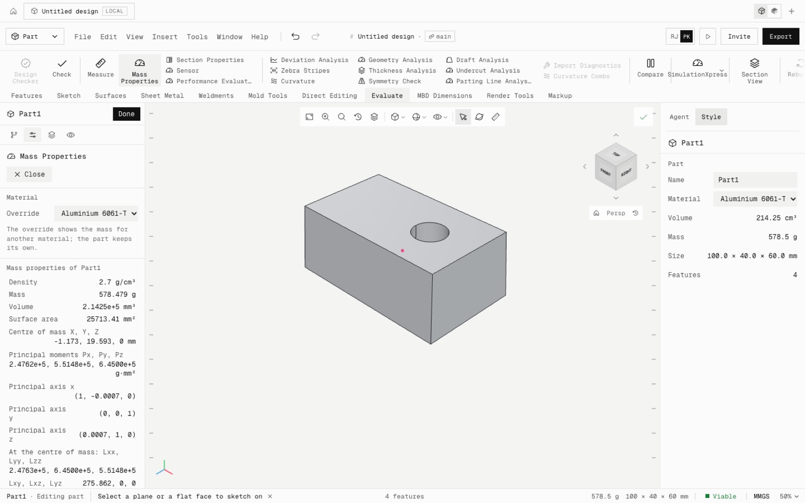
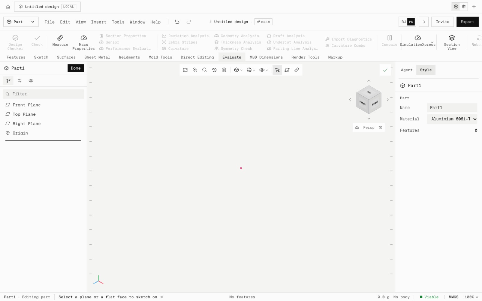
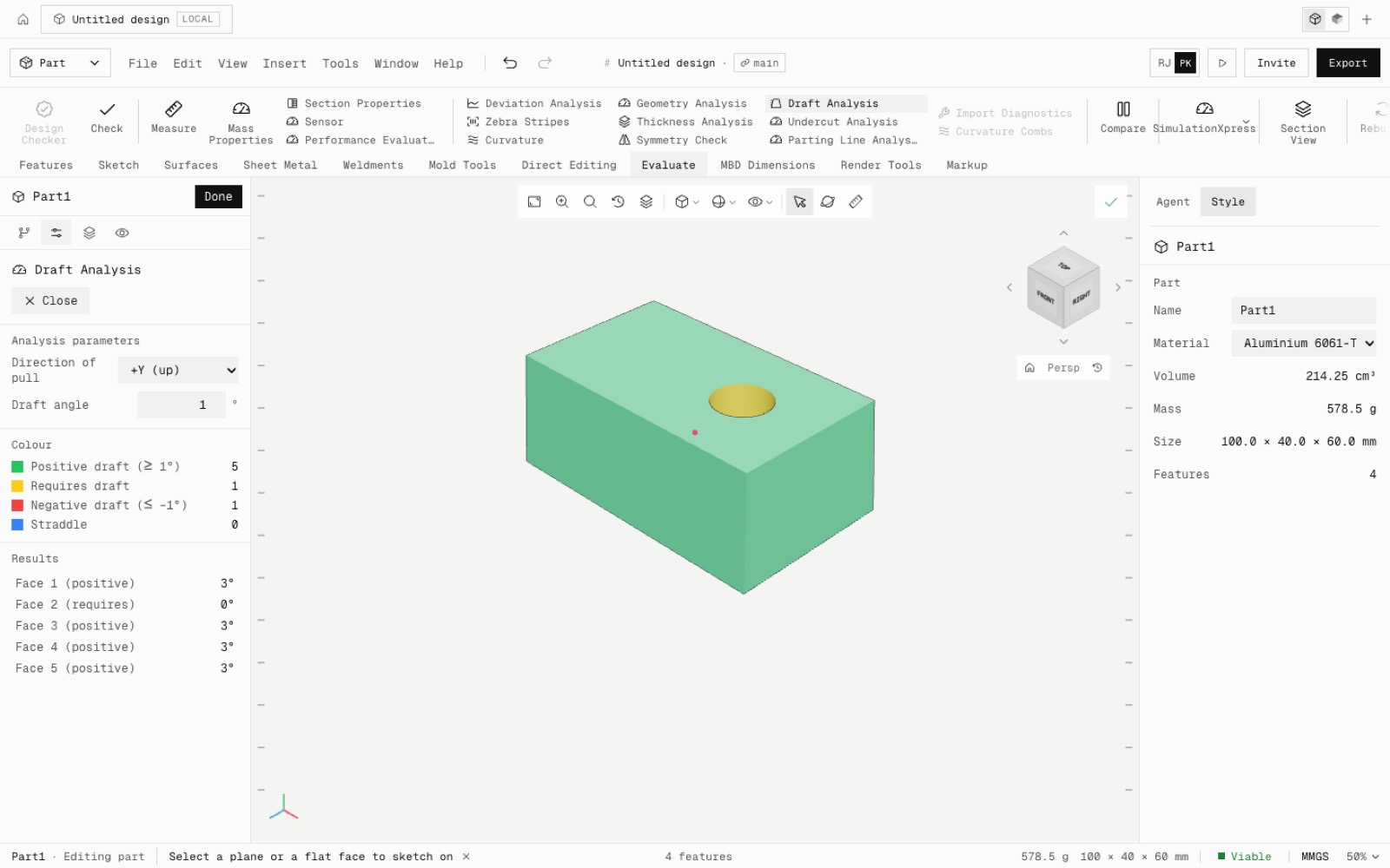
The Evaluate tab works. Mass Properties and Section Properties come from the exact solid, Measure picks vertices, edges and faces, and Check finds bad geometry. Draft, undercut, parting line, thickness, curvature, zebra, deviation and symmetry analyses colour the part. Equations and global variables drive dimensions (type = in a value field), and configurations and a design table make variants of one part. Custom properties and sensors round it out.

After: The Evaluate tab before (mostly greyed) and after (lit), with Mass Properties open
Before: The Evaluate tab before (mostly greyed) and after (lit), with Mass Properties open
BeforeAfter
Evaluate and Mass Properties
Draft analysis colouring a part's faces by draft angle
Draft analysis
The Equations dialog with global variables driving dimensions
Equations
The ConfigurationManager with configurations of one part
Configurations

Mass Properties gives mass, volume, area, centre of mass, principal axes and moments of inertia. A 100 × 50 × 20 block reads exactly m(b²+c²)/12 about its centroid, a cylinder mr²/2, and a block turned 30° has its principal axis at 30.0000°. Section Properties matches bh³/12 for a rectangle.

The analyses colour the part and never change it. A face drafted 3° reads 3.000°, a 2 mm shell reads 2.000 mm thick, and a Ø20 cylinder reads curvature 0.1 /mm.

Equations and global variables run on every rebuild. Width = 120 rebuilds a block to 120 × 40 × 30, and typing ="Width"/4 into a depth gives 30. Configurations switch suppression and values, the design table builds variants from a grid, and every change is one undo step the agent can make too.

Not yet: curvature combs, Design Checker, costing, mass and centre-of-mass overrides, = in every number field, and title blocks reading custom properties. Core parity is now 113 of 239.

Added
  • Mass and Section Properties, Measure, Check
  • Draft, undercut, parting line, thickness, curvature, zebra, deviation and symmetry analyses
  • Equations, global variables, link values
  • Configurations and design tables
  • Custom properties and sensors
  • npm run test:evaluate
Shipped in
e12479f
Featurev2.57

Weldments and Mold Tools: structural frames with cut lists, and core and cavity splits

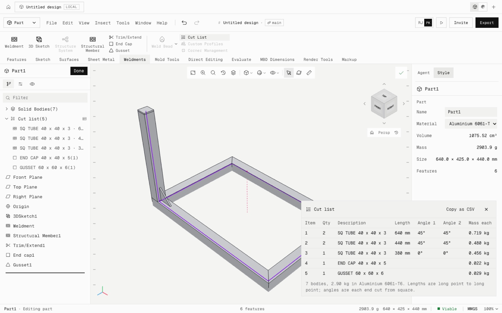
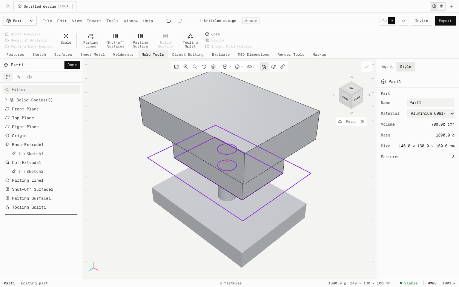
The Weldments tab builds welded frames: 3D sketch, structural members from 47 ISO and EN profiles (square and rectangular tube, pipe, angle, UPE channel, IPE beam), trim/extend, end caps, gussets, fillet beads, and a cut list with lengths and end angles. The Mold Tools tab has parting lines with draft analysis, shut-off surfaces, a parting surface, tooling split into core and cavity, and side cores.

After: The Weldments tab before (all greyed) and after (lit), with a welded tube frame and its cut list
Before: The Weldments tab before (all greyed) and after (lit), with a welded tube frame and its cut list
BeforeAfter
Weldments
The Mold Tools tab with a part split into core and cavity, exploded
Mold Tools

Structural members sweep a profile along sketch lines, each member its own body, in groups with end miter or end butt corners, a weld gap, mirror and rotation. A 600 × 400 frame of 40 × 40 × 3 tube mitred at the corners lists 2 × 640 and 2 × 440 in the cut list, every end 45°. The cut list table copies as CSV with mass.

Tooling Split divides a block around the part into core and cavity bodies, and their volumes add back up to the block exactly. Core pulls a side core out of a block. Scale handles shrinkage.

Tested by hand in the app: a welded frame from a 3D sketch, two member groups, a trim, an end cap, a gusset and the cut list, then a mold split on a second part. The volumes match the closed forms.

Not yet: Weld Bead, Groove Bead, custom profiles, Structure System, members along arcs, splines and picking in the 3D sketch, curved parting lines, and the cut-list table on drawings. Core parity is now 103 of 239.

Added
  • 3D sketch (lines)
  • Structural members with a 47-profile ISO/EN library
  • Trim/Extend, End Cap, Gusset, Fillet Bead, Cut List
  • Parting Lines, Shut-off Surfaces, Parting Surface, Tooling Split, Core
  • npm run test:weld
Shipped in
f095f19
Featurev2.56

The Sheet Metal tab: flanges, hems, bends and a true flat pattern

Sheet metal parts can be made by hand. Base Flange/Tab, Edge Flange, Miter Flange, Hem, Jog, Sketched Bend, Break Corner, Closed Corner, forming tools (dimple, louver), Normal Cut, Unfold, Fold and Flatten are all here. Gauge tables set thickness, bend radius and K-factor, and the flat pattern exports as DXF with bend lines.

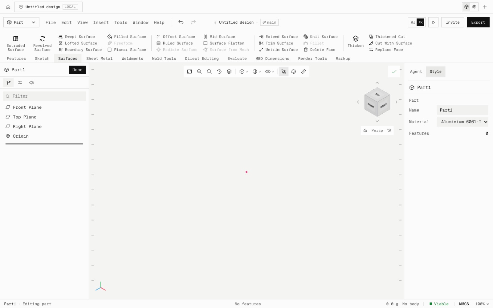
After: The Sheet Metal tab before (all greyed) and after (14 commands lit)
Before: The Sheet Metal tab before (all greyed) and after (14 commands lit)
BeforeAfter
The Sheet Metal tab
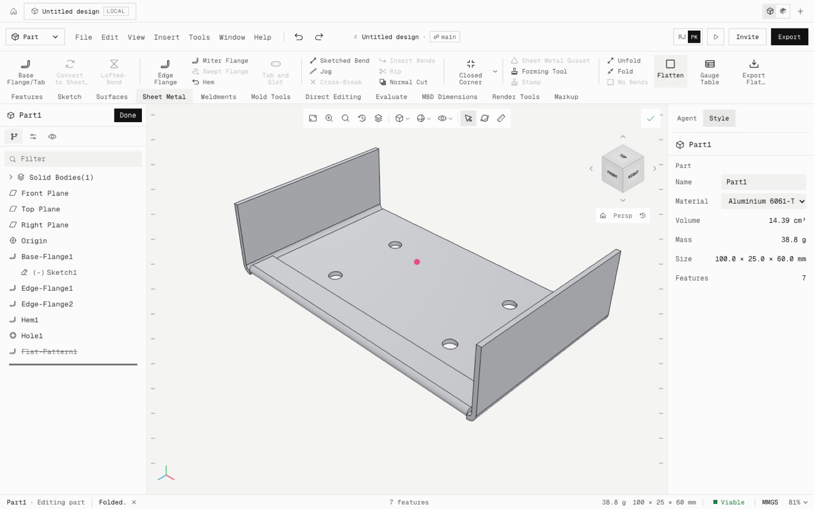
A 16-gauge steel bracket built by hand: base flange, two edge flanges, a hem and four holes
Built by hand
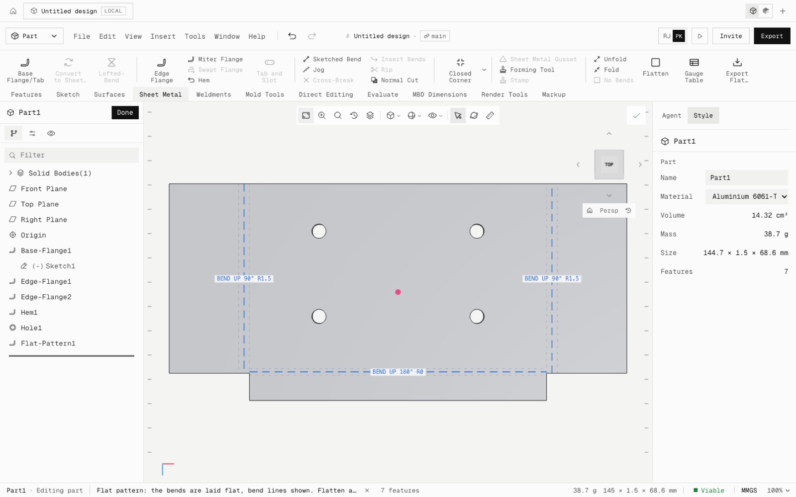
The bracket flattened, with bend lines and bend notes
Flat pattern

The flat pattern is computed from the bends, not estimated. Each bend unrolls about its axis and slides out by its bend allowance, BA = π/180 · θ · (R + K·T). A 90° bend at R2, T2, K0.44 in an L-bracket develops to exactly 126.524 mm. Hems, jogs and U channels match their closed forms too, and Unfold then Fold round-trips.

Tested by hand in the app: an electronics bracket in 16-gauge steel, with a base flange, two edge flanges picked in the canvas, a closed hem and four M4 holes. It flattens to 144.736 × 68.581 mm, the closed form. A Flat-Pattern row in the FeatureManager toggles the flat view, which shows bend lines with notes such as BEND UP 90° R1.5.

Cuts made while unfolded land in the right place when folded again. The agent has all 14 sheet metal tools.

Not yet: Convert to Sheet Metal, Insert Bends, Rip, Lofted Bend, Swept Flange, cuts across a bend region surviving unfold, multi-edge flanges, and the flat-pattern drawing view. Core parity is now 101 of 239.

Added
  • 14 sheet metal commands
  • Gauge tables and K-factor bend allowance
  • Flat pattern with bend lines, DXF export
  • npm run test:sheetmetal
Shipped in
ef4b80f
Featurev2.55

The Surfaces tab: 20 surface commands, from extruded and lofted to knit and thicken

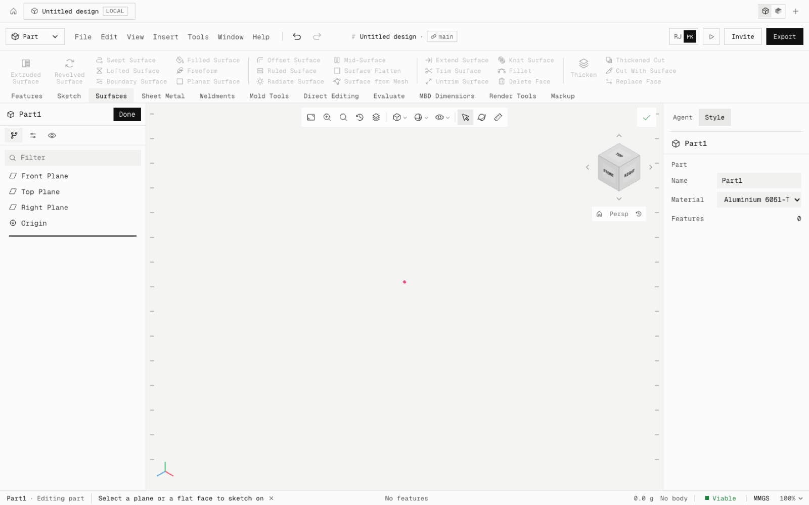
Surface modelling works. You can make extruded, revolved, swept, lofted, boundary, planar, offset, ruled and filled surfaces, then knit, trim, untrim, extend and thicken them into solids. Thickened Cut, Cut With Surface, Mid-Surface, Surface Flatten, Delete Face (delete, patch or fill) and Replace Face are there too. Surface bodies show as translucent sheets in their own Surface Bodies folder.

After: The Surfaces tab before (every button greyed) and after (20 surface commands lit)
Before: The Surfaces tab before (every button greyed) and after (20 surface commands lit)
BeforeAfter
The Surfaces tab
A lofted surface trimmed, closed, knitted and thickened 2 mm into a solid
Loft, trim, knit, thicken
Delete Face turning the picked faces into a surface body
Delete Face

Surfaces are open shells kept beside the solid. They knit into a solid (Knit with Create solid), thicken into one, or cut it. Each command is checked against closed forms in the kernel. Knitting the six faces of a box gives exactly its volume, thickening a 100 × 60 surface by 5 gives 30,000 mm³, and flattening a half cylinder gives its exact area.

Tested by hand in the app: a loft between two sketches, trimmed at a plane, closed with a planar surface, knitted and thickened 2 mm. The solid matched its closed form, 3420 mm³, with one undo step per command.

Surfaces work with multibody parts: thickened and knitted solids go through the same Merge result rules as extrudes.

Not yet: Radiate Surface, fillets on surfaces, Freeform, Surface from Mesh, guide curves on surface lofts, surfaces in the assembly view and in STEP export. Core parity is now 94 of 239.

Added
  • 20 surface commands
  • Surface Bodies folder
  • npm run test:surfaces
Shipped in
6d44691
Featurev2.54

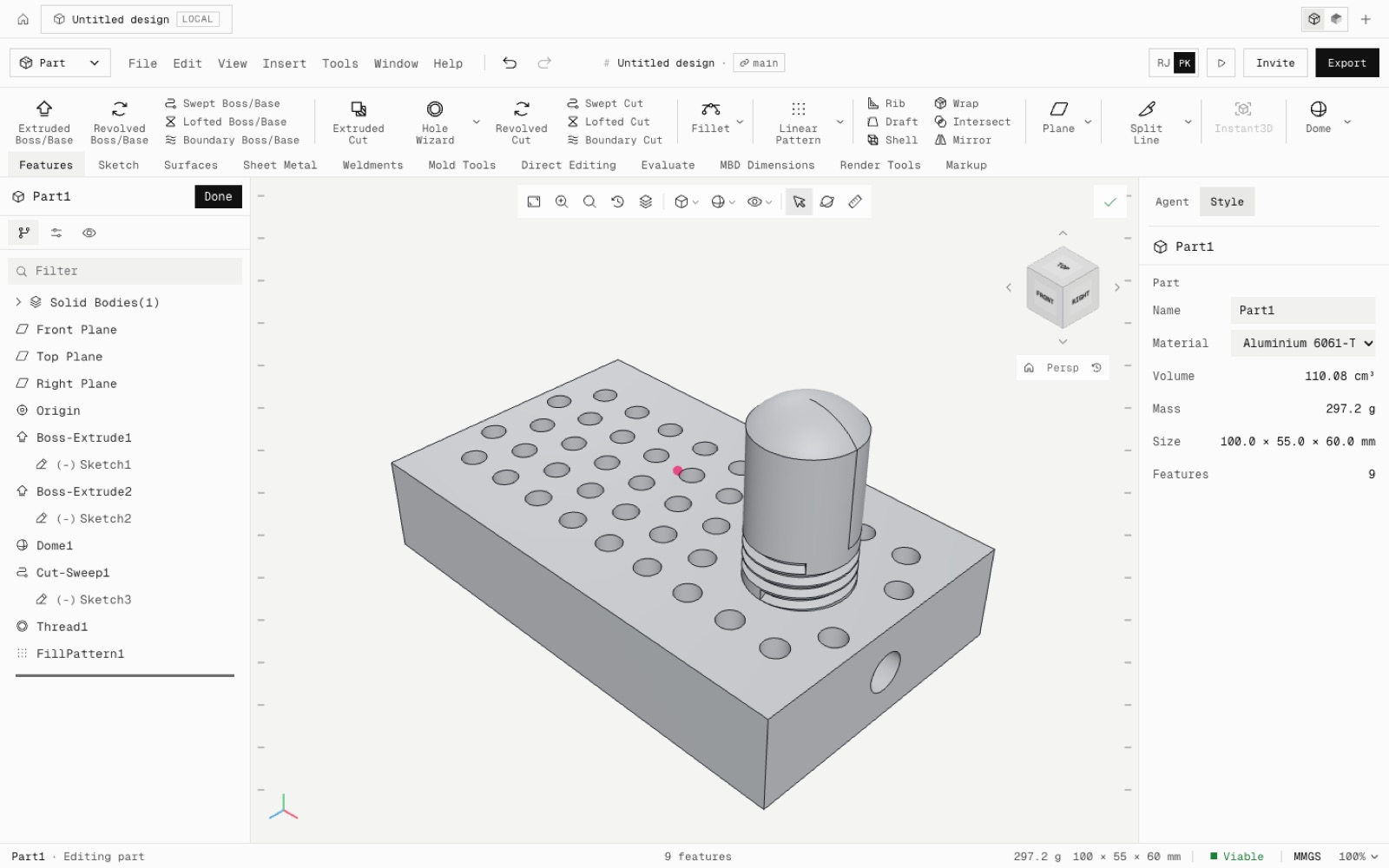
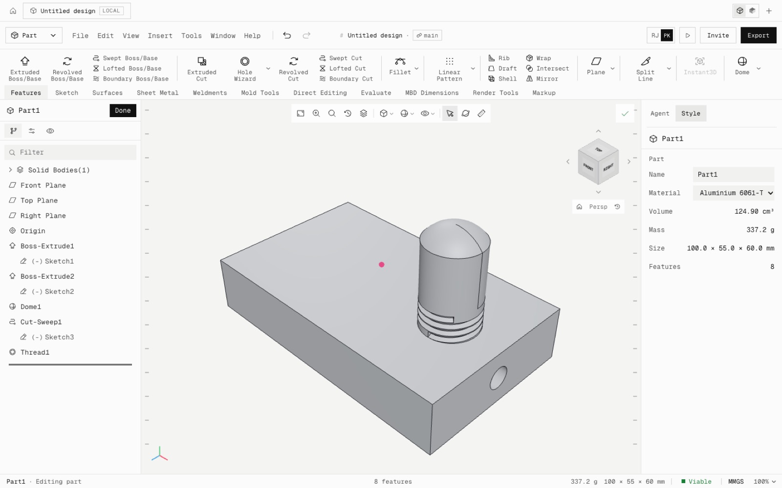
13 more part features: swept, lofted and revolved cuts, boundary, dome, threads, wrap and four patterns

The Features tab gains Swept Cut, Lofted Cut, Revolved Cut, Boundary Boss/Base and Boundary Cut, Dome, Thread and Cosmetic Thread, Curve-, Sketch- and Table-Driven patterns, Fill Pattern and Wrap. Revolve, Hole Wizard, Shell, Rib, Draft and Fillet gain the main options SolidWorks has. Every core part feature in our SolidWorks list is now done or partly done.

After: The Features tab before (cuts, boundary, dome, thread, wrap and patterns greyed) and after (lit)
Before: The Features tab before (cuts, boundary, dome, thread, wrap and patterns greyed) and after (lit)
BeforeAfter
The Features tab
One part built by hand with a dome, a swept cut, a thread and a fill pattern of holes
Built by hand
A modelled thread on a shaft
Thread

Each one is checked against its closed form in the kernel. A swept cut removes exactly π·5²·100, a boundary along a quarter arc gives π·5²·(π/2·40), and a dome gives the spherical cap πh(3a²+h²)/6. A modelled M6 thread is within 0.001 % of its helical volume, and fill patterns place exactly 45, 43 and 38 holes for square, staggered and circular layouts.

New options: Revolve has Direction 2, Mid-Plane and Thin Feature. Sweep takes a circular profile without a sketch, and Loft a centerline. Hole Wizard adds slots, counterbore slots and tapered pipe taps. Shell can go outward with different thicknesses on chosen faces. Rib has draft, Draft has parting line, and Fillet has chord width.

Thread picks the right size from the shaft: a Ø20 shaft gets M20 × 2.5 at the ISO coarse pitch.

Not yet: Variable Pattern, solid-body sweeps, sweep and loft guide curves, loft end tangency, step draft, Hole Series and Stud Wizard. Modelled threads take 3 to 4 s to rebuild. Core parity is now 89 of 239.

Added
  • Swept, Lofted and Revolved Cut
  • Boundary Boss/Base and Cut
  • Dome
  • Thread and Cosmetic Thread
  • Curve-, Sketch-, Table-Driven and Fill patterns
  • Wrap
  • npm run test:features2
Improved
  • Revolve, Hole Wizard, Shell, Rib, Draft and Fillet options
Shipped in
842f89f
Featurev2.53

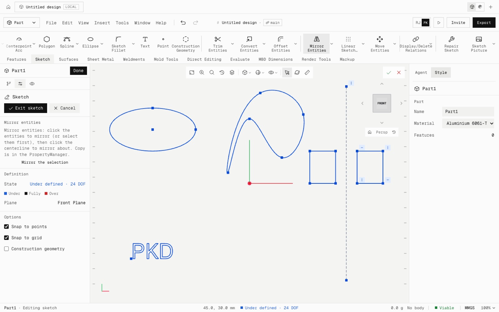
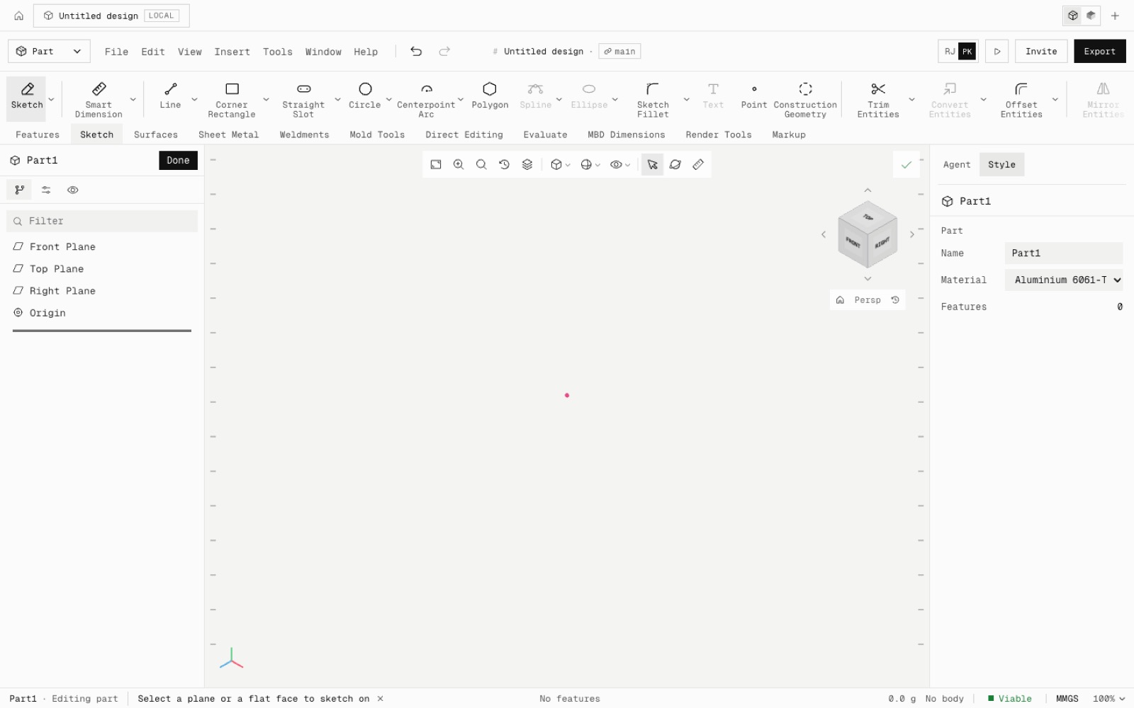
The full sketch toolset: ellipse, spline, text, mirror, patterns, convert entities and more

The Sketch tab now has 34 more SolidWorks sketch commands. Entities: ellipse, partial ellipse, spline, parabola, conic, sketch text, 3-point rectangles, parallelogram, slots, perimeter circle and midpoint line. Tools: mirror and dynamic mirror, linear and circular sketch patterns, convert entities, intersection curve, extend, split, move, copy, rotate, scale and stretch, sketch chamfer, jog line, fix, make path and repair sketch.

After: The Sketch tab before (most commands greyed) and after (ellipse, spline, text, mirror and patterns lit), with a rectangle mirrored about a centerline
Before: The Sketch tab before (most commands greyed) and after (ellipse, spline, text, mirror and patterns lit), with a rectangle mirrored about a centerline
BeforeAfter
The Sketch tab
One sketch with an ellipse, a spline, the text PKD, mirrored rectangles and a pattern of circles, extruded 10 mm
Drawn by hand, then extruded

Copies stay defined. Mirrors, patterns and copies are held by their own relations, so a fully defined seed gives fully defined copies with no redundant relations. A pattern's spacing is a dimension, so editing it moves every copy.

The kernel gets exact geometry: ellipses are true ellipse edges, and splines, parabolas and text are B-spline edges. An ellipse extrude is exactly πab·h, a half ellipse revolves into exactly 4/3·πab², and a sweep along a spline now keeps its profile square to the path (it used to lose 2.5 % of its volume at a bend).

Sketch Text uses the Geist typeface (SIL Open Font License, licence included in public/fonts).

Fixed: a ribbon flyout menu opened under the canvas, so clicking one of its items landed on the sketch.

Not yet: spline curvature handles, text along a curve, the conic as one exact edge, angle-distance sketch chamfers, and convert entities that relink when the model changes. Sketch parity is now 87 of 239 core commands overall.

Added
  • 34 sketch entities and tools
  • npm run test:sketch-complete
Fixed
  • Ribbon flyout menus opened under the canvas
  • Sweeps along splines lost volume at inflections
Shipped in
caa8d90
Featurev2.52

Multibody parts, Combine, Split, Scale, Move Face, helices and curves

Parts can now hold several bodies. Extrude, revolve, sweep and loft have a Merge result check box, and a Solid Bodies folder lists the bodies. Combine (add, subtract, common), Intersect, Split, Move/Copy Body, Delete/Keep Body, Scale, Indent and Insert Part work on them. Move Face and Delete Face edit faces directly. Reference points, coordinate systems and six kinds of curve (helix and spiral, split line, projected, composite, and through XYZ or reference points) are new.

After: The Direct Editing tab before (every button greyed) and after (Combine, Split, Intersect, Indent, Move Face and Scale lit)
Before: The Direct Editing tab before (every button greyed) and after (Combine, Split, Intersect, Indent, Move Face and Scale lit)
BeforeAfter
Direct Editing tab
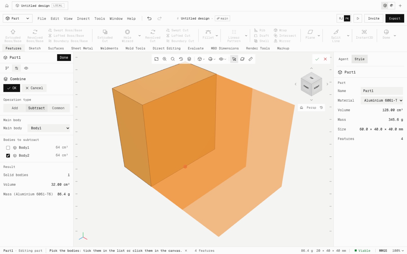
Combine set to Subtract, with the main body picked and the preview at 32.00 cm³
Combine
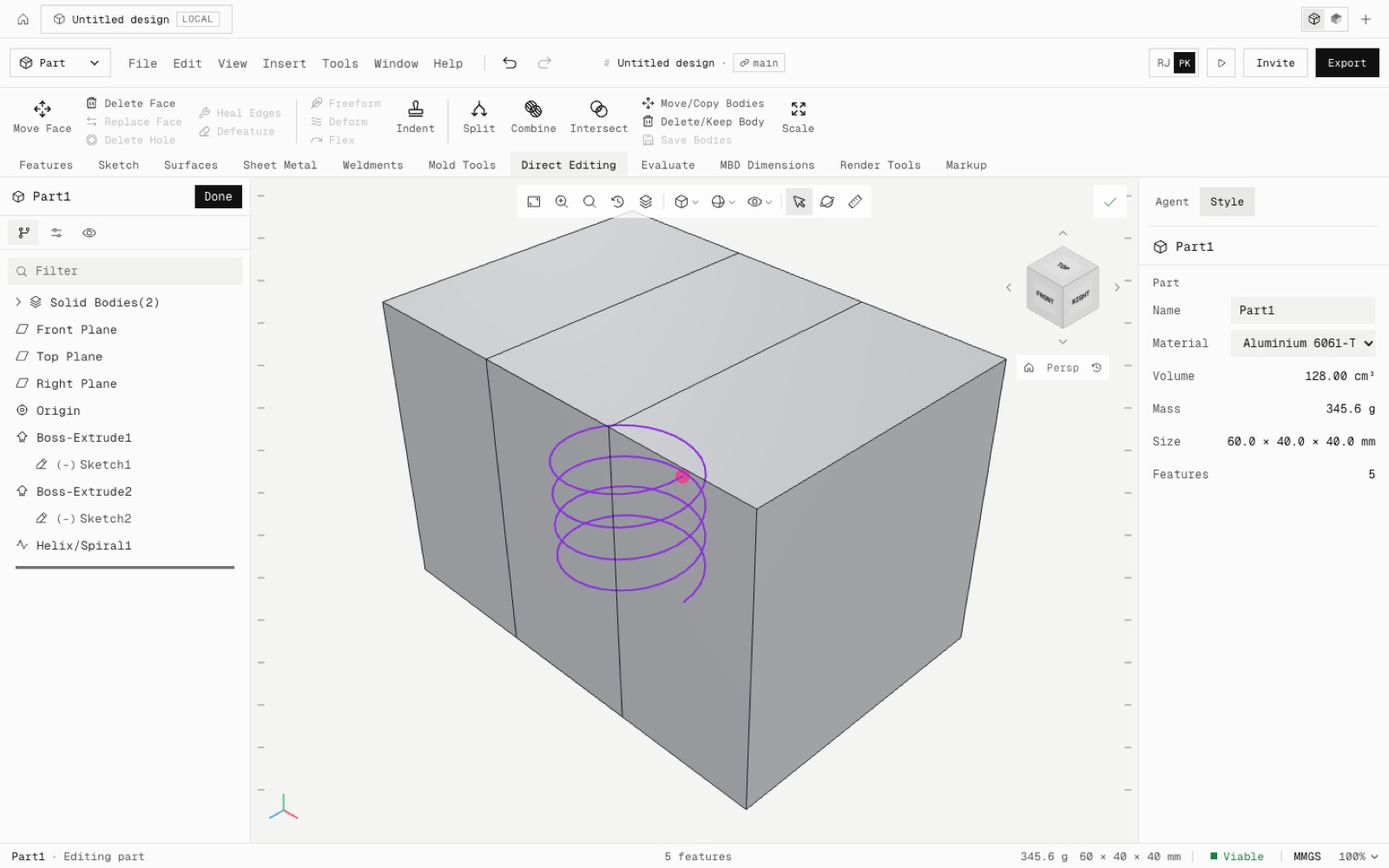
A helix of 4 turns drawn on the part, 252.122 mm long
Helix

Every command is checked against closed forms in the real kernel. Combine-subtract gives A − A∩B. A split's pieces add up to the body. Scale ×2 gives 8× the volume. Move Face grows a Ø10 hole to exactly Ø14. A 4-turn helix of radius 10 over 20 mm measures √((2π·10·4)² + 20²) = 252.122 mm.

The Direct Editing tab now lights up Combine, Split, Intersect, Indent, Move Face and Scale. The reference geometry and curve flyouts on the Features tab light up Point, Coordinate System, Helix/Spiral, Split Line, Projected Curve, Composite Curve and the two through-points curves. Planes gain Mid plane and Normal to line.

The agent can use all of them; its tools come from the same commands.

Not yet: non-uniform scale, Move Face translate and rotate, silhouette split lines, tangent planes, arc-centre points, a linked Insert Part, and Mate Reference.

Added
  • Multibody parts and Solid Bodies folder
  • Combine, Intersect, Split, Move/Copy Body, Delete/Keep Body, Scale, Indent, Insert Part
  • Move Face, Delete Face
  • Reference point, Coordinate system, Mid plane, Normal-to-line plane
  • Helix/Spiral, Split Line, Projected, Composite and point curves
  • npm run test:bodyops
Shipped in
35eb38e
Featurev2.51

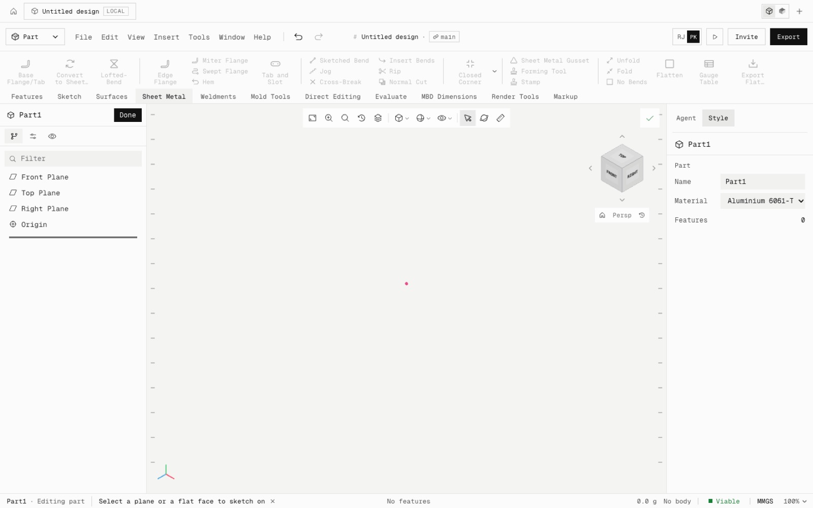
Every SolidWorks command on the ribbon, a File · Edit · View · Insert menu bar, and a clean canvas

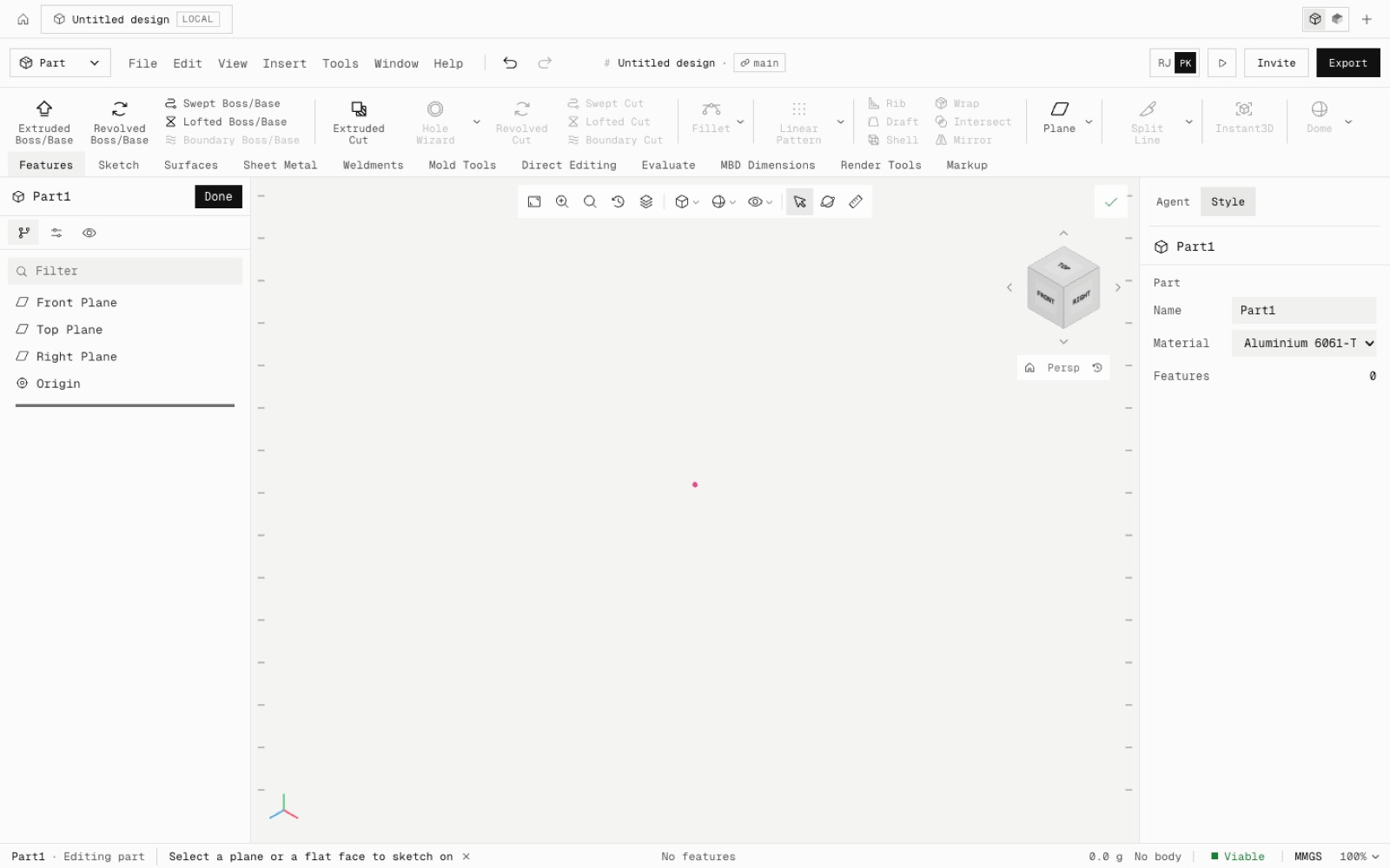
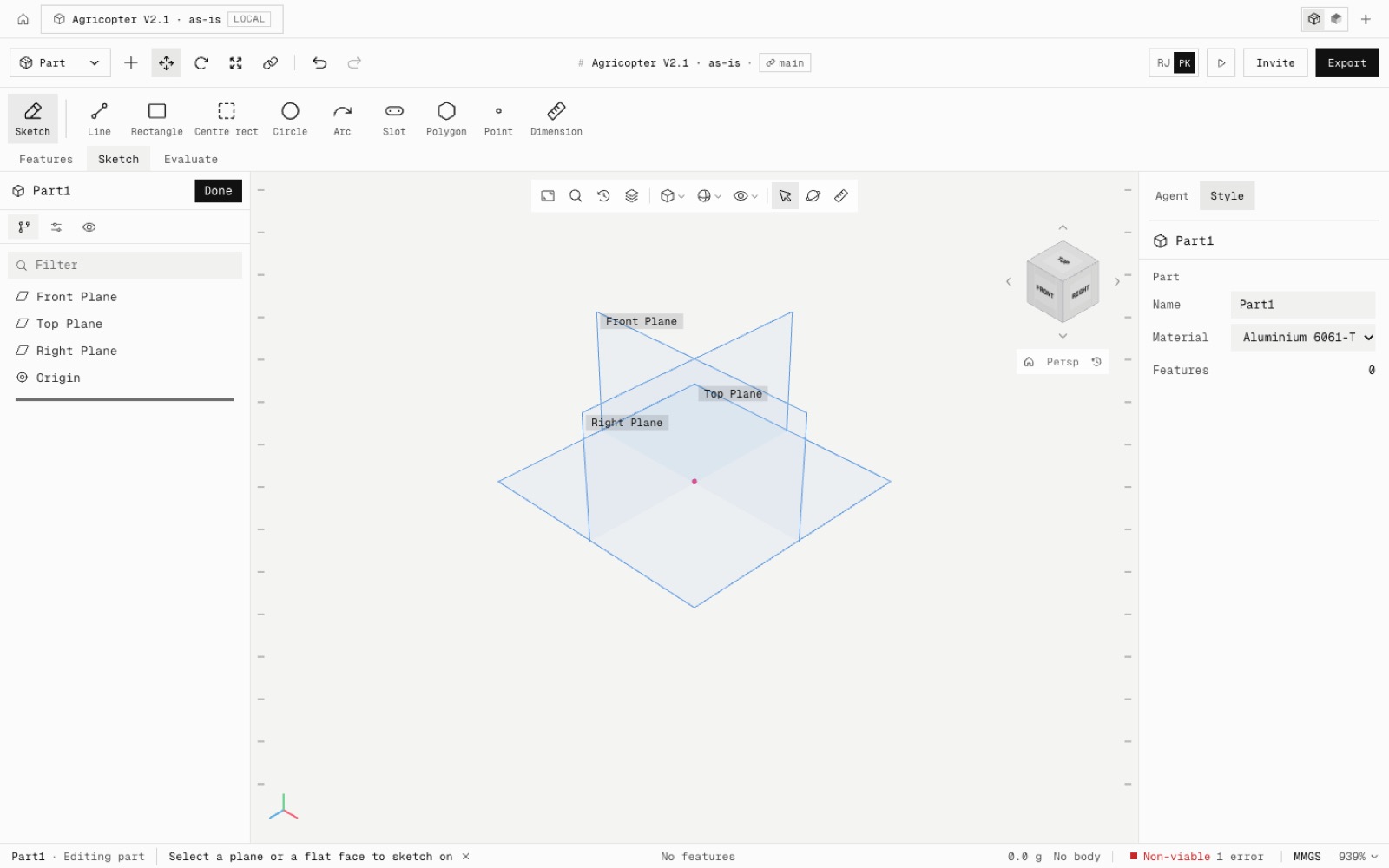
The part editor now shows the whole SolidWorks command set: 11 CommandManager tabs (Features, Sketch, Surfaces, Sheet Metal, Weldments, Mold Tools, Direct Editing, Evaluate, MBD Dimensions, Render Tools, Markup), a classic menu bar, and ⌘K searching all 467 commands. 78 work today. The rest stay in their places, greyed with "Not built yet", and light up as they are built. A blank part shows only the origin and the triad.

After: The new part before (sketch tools only, planes shown) and after (the full Features tab with every SolidWorks command, the menu bar, and a blank canvas with only the origin and triad)
Before: The new part before (sketch tools only, planes shown) and after (the full Features tab with every SolidWorks command, the menu bar, and a blank canvas with only the origin and triad)
BeforeAfter
The whole command set
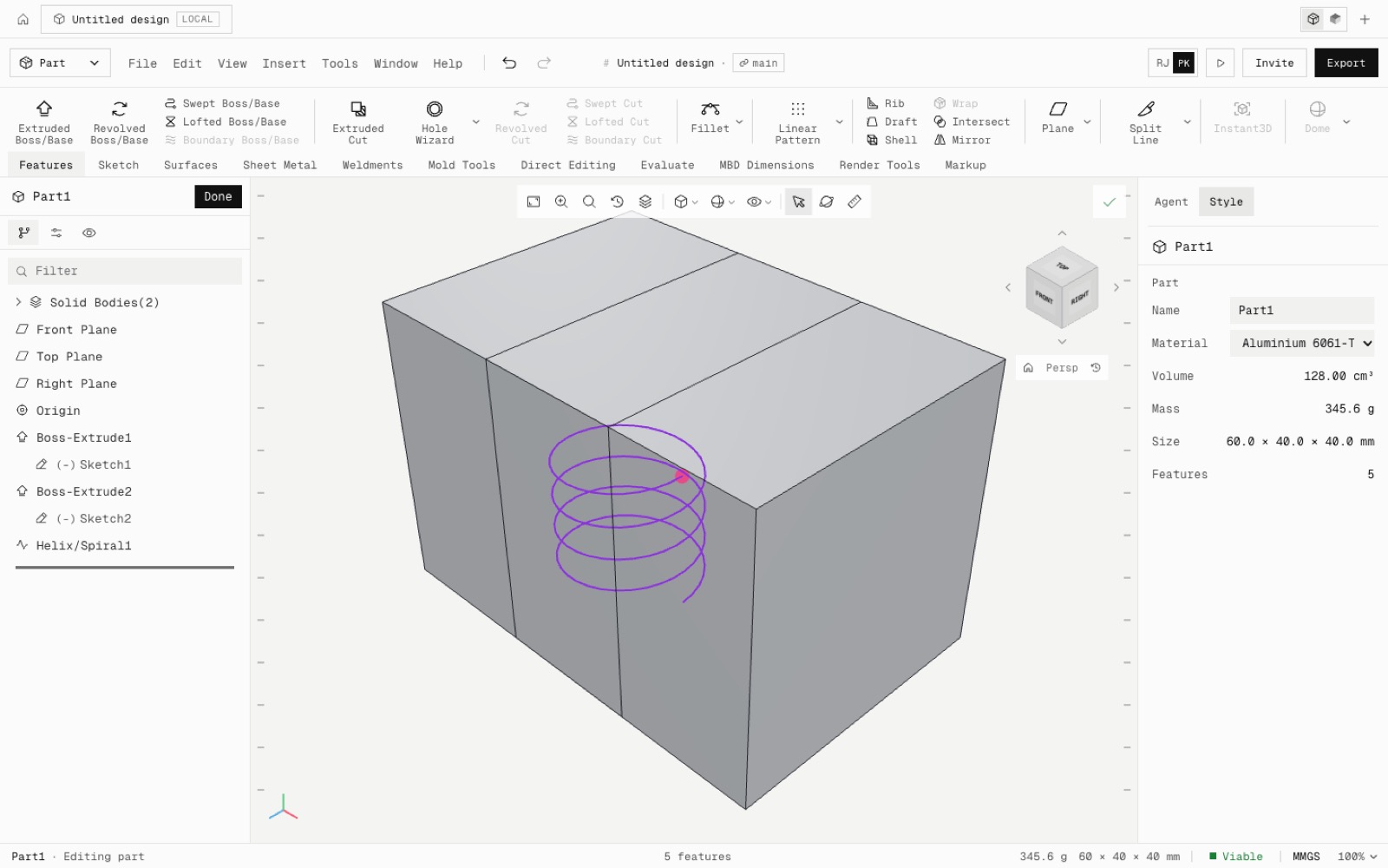
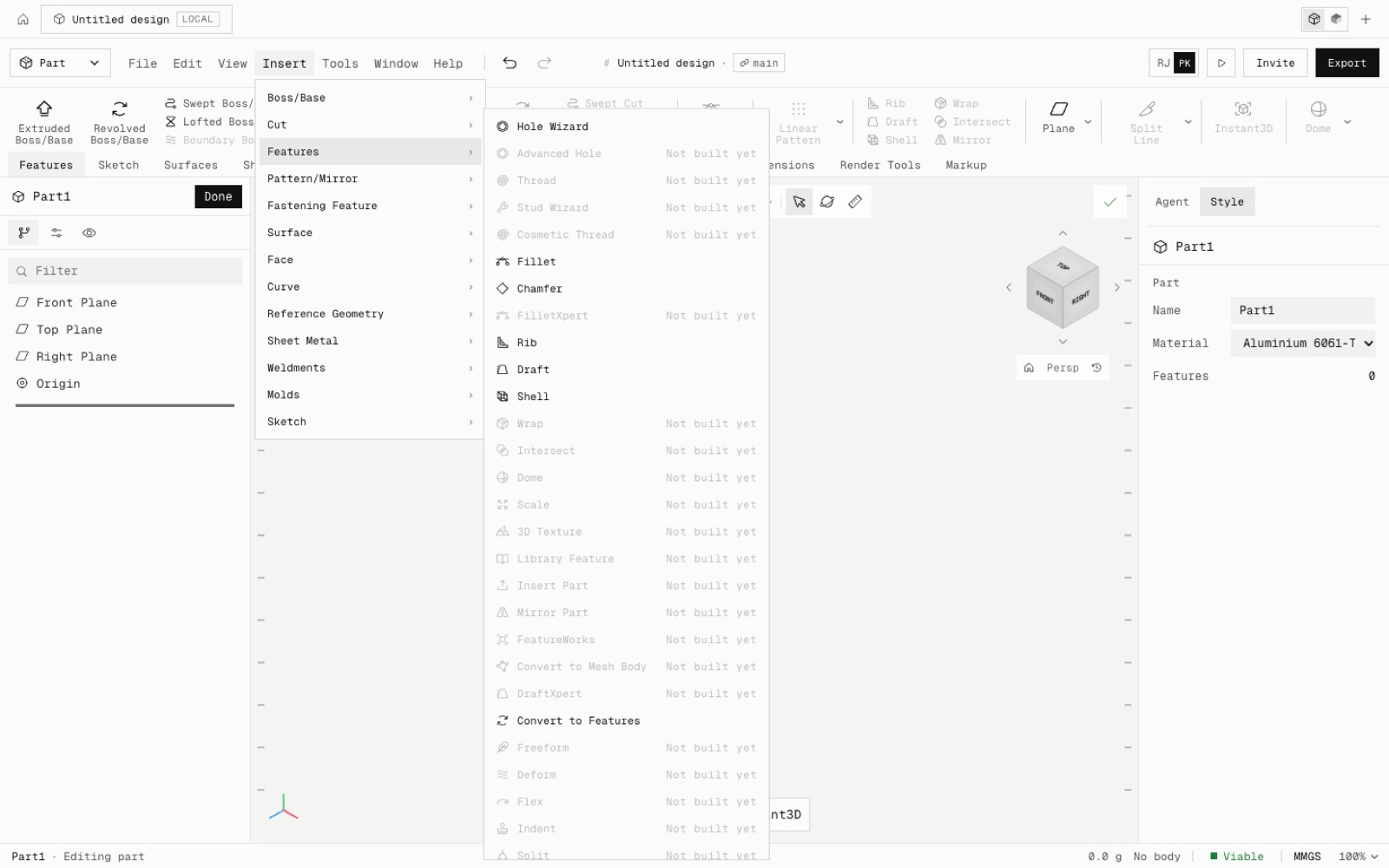
Insert → Features: Hole Wizard, Fillet, Chamfer, Rib, Draft and Shell available, the rest marked Not built yet
The Insert menu
The Sheet Metal tab: every command in place, greyed until built
Sheet Metal tab

One catalog of all 467 commands from our SolidWorks parity list drives the ribbon, the menu bar and Quick actions (⌘K). A command is enabled the moment it exists in the command registry, so each new feature turns its button on without layout changes.

The ribbon follows SolidWorks' order, with separators, flyouts with chevrons and stacked small buttons. It scrolls sideways when a tab is wider than the window and switches to small icons below 1440 px. Commands that need a solid stay grey until there is one.

The menu bar (File, Edit, View, Insert, Tools, Window, Help) sits in the top bar. Insert has SolidWorks' 13 submenus: Boss/Base, Cut, Features, Pattern/Mirror, Fastening Feature, Surface, Face, Curve, Reference Geometry, Sheet Metal, Weldments, Molds and Sketch.

A new part shows only the origin and the triad. The Front, Top and Right planes appear when you start a sketch or hover their row, and the floor grid stays off while a part is open, so a sketch on Front looks straight at it. Assembly and Drawing workspaces get their own tab sets.

Built so far: 78 of 440 distinct commands. Surfaces, Sheet Metal, Weldments, Mold Tools and Direct Editing are next.

Added
  • Full CommandManager: 11 part tabs
  • Menu bar: File, Edit, View, Insert, Tools, Window, Help
  • Quick actions search all 467 commands
  • npm run test:command-catalog
Improved
  • Blank part shows only the origin and triad
  • Planes appear when picking a sketch plane
  • No floor grid while editing a part
Shipped in
dbec19f
Featurev2.49

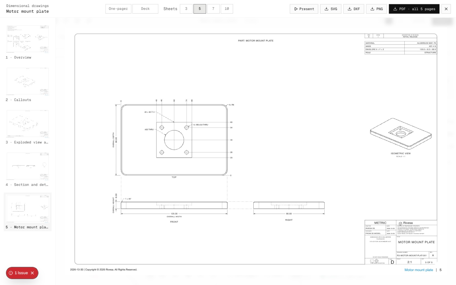
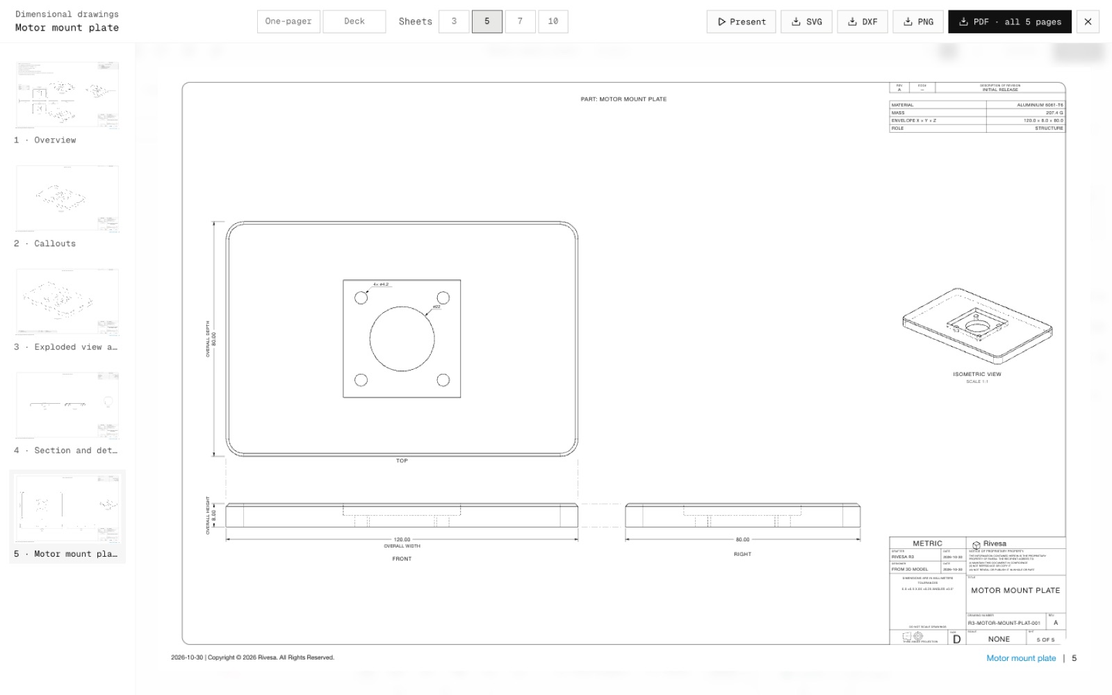
Hole callouts from the Hole Wizard, ordinate hole positions, and holes that read as holes

Drawings now call out holes the way they were made: 4× M5×0.8 THRU for tapped holes, with the counterbore, countersink and clearance symbols. The part sheet places every hole by ordinate dimensions from a datum corner and dimensions the pocket, fillets and chamfer. The isometric views no longer make holes look like posts.

After: The motor mount plate's part sheet before (holes called ⌀4.2, no positions) and after (4× M5×0.8 THRU, ordinate hole positions, 40 × 40 ▽ 4, 4× R6, 1 × 45°)
Before: The motor mount plate's part sheet before (holes called ⌀4.2, no positions) and after (4× M5×0.8 THRU, ordinate hole positions, 40 × 40 ▽ 4, 4× R6, 1 × 45°)
BeforeAfter
The part sheet
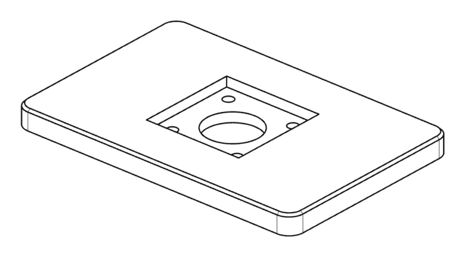
After: The isometric view before (dashed hole walls read as posts) and after (hidden lines removed, holes read as holes)
Before: The isometric view before (dashed hole walls read as posts) and after (hidden lines removed, holes read as holes)
BeforeAfter
Isometric holes

Each projected hole is matched to its Hole Wizard feature, pattern and mirror copies included, and identical holes are grouped. Tapped: M5×0.8 THRU, or M5×0.8 ▽ 10 with the ⌀4.2 tap drill. Counterbore: ⌀5.5 THRU, ⌴ ⌀9.5 ▽ 5.4. Countersink: ⌀5.5 THRU, ⌵ ⌀11.2 × 90°. Clearance: ⌀5.3 THRU with its ISO 273 fit. A round cut reads ⌀22 THRU.

On the motor mount plate's sheet, the hole centres are dimensioned from the datum corner: X 0, 40, 46, 60, 74, 80 and Y 0, 20, 26, 40, 54, 60. The pocket reads 40 × 40 ▽ 4, the corners 4× R6 and the edge 1 × 45°. Holes get centre marks, and side views get centrelines. Every value is measured from the solid, and no text overlaps another or a drawn edge.

Isometric and exploded views are drawn with hidden lines removed, as is usual for pictorial views. The dashed hole walls under each rim had made holes read as pegs. Short hidden edges in the standard views get a finer dash so they still read as hidden.

Added
  • Hole Wizard callouts on drawings
  • Ordinate hole positions
  • Pocket, fillet and chamfer callouts
  • npm run test:drawing-callouts
Fixed
  • Tapped holes were called out by their drill size
  • Holes looked like posts in isometric views
  • Short dimensions printed their value over their arrows
Shipped in
4f991a8
Featurev2.50

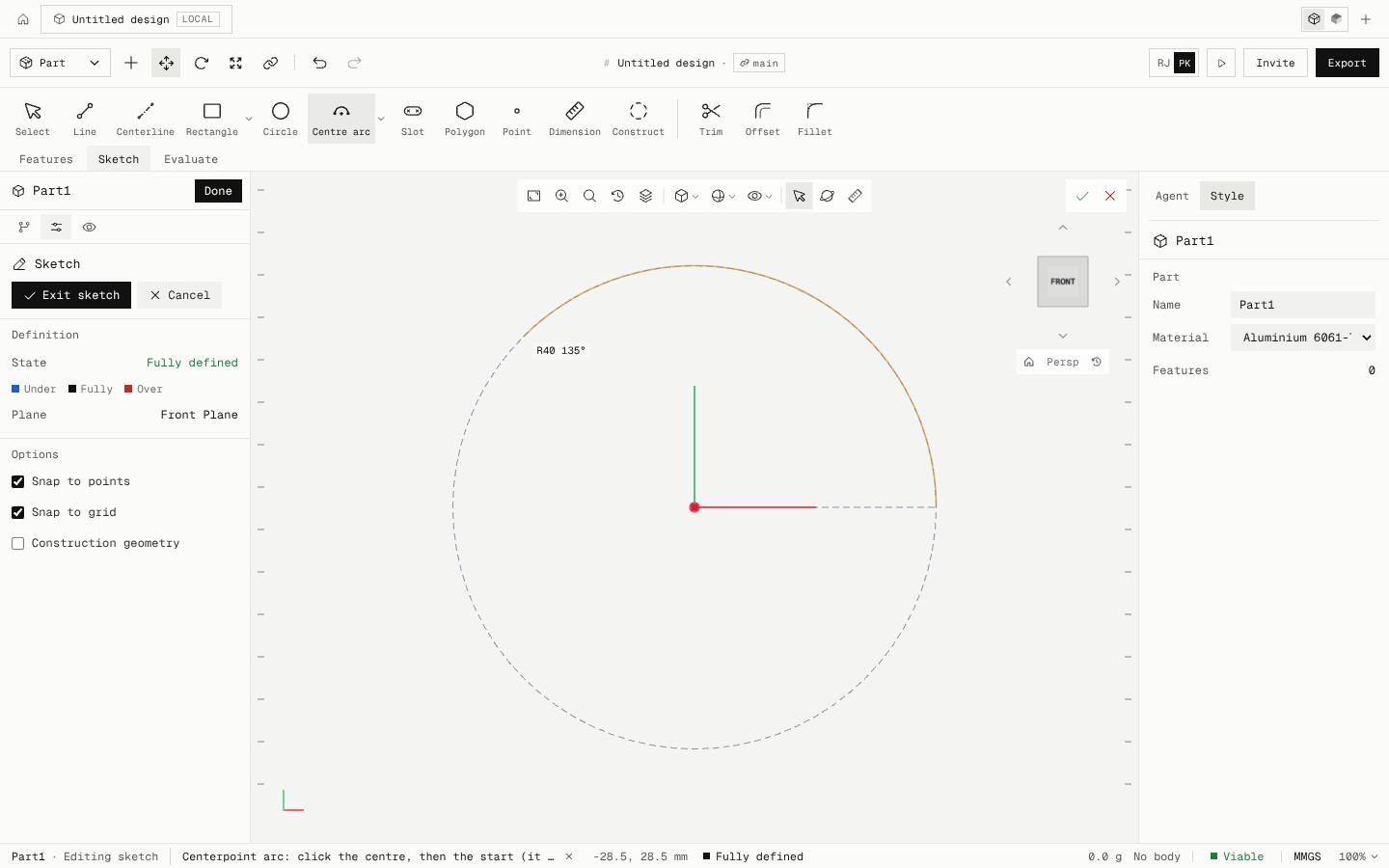
Centerpoint arc in the sketch Arc flyout

Sketches get the Centerpoint arc: click the centre, then the start (which sets the radius), then the end. The arc runs the way you move the cursor round, with the circle shown as a guide and the radius and angle next to the cursor. Core SolidWorks parity is now 77 of 239 commands done.

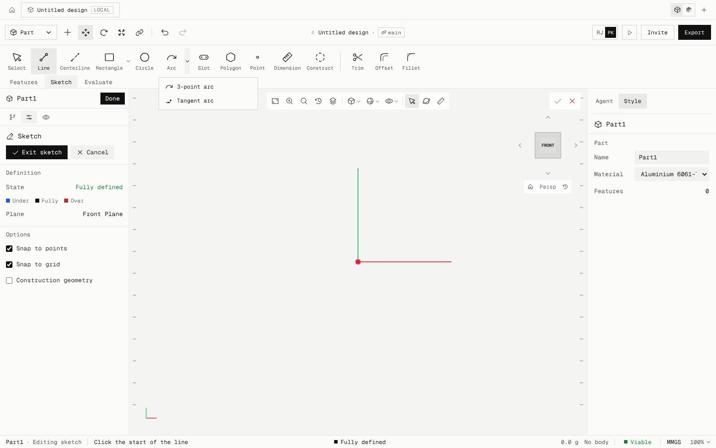
After: The sketch Arc flyout: before, 3-point and Tangent arc only; after, a Centerpoint arc being placed on Front, R40 swept 135° with the circle shown as a guide
Before: The sketch Arc flyout: before, 3-point and Tangent arc only; after, a Centerpoint arc being placed on Front, R40 swept 135° with the circle shown as a guide
BeforeAfter
Centerpoint arc

The Arc flyout lists 3-point arc, Centerpoint arc and Tangent arc. The end click only sets the angle, so the end always lands on the circle; clicked on an existing point that is already on the circle (the origin too), the arc reuses it, so a chord drawn first closes the profile.

Move anticlockwise from the start for an anticlockwise arc, clockwise for a clockwise one. An arc can't go a full turn: use Circle for that. Construction mode makes it a reference arc, and each arc is one undo step, the same as the agent's model.sketch arc.

Added
  • Centerpoint arc sketch tool
Improved
  • SolidWorks parity: 77 of 239 core commands done
Try it

Open a sketch, open the Arc flyout and pick Centerpoint arc.

Open Speed
Shipped in
3e3620e
Improvementv2.49

SolidWorks parity recounted: 76 of 239 core commands done

The SolidWorks parity list had not been updated since 26 October, so it undercounted what shipped in v2.34 to v2.48. Every core row was checked again against the code: 35 rows moved up, none down, and the core done share is now 76 of 239 (32 %, was 61). A new check recomputes the totals from the rows, so the number can't drift from the list again.

Rows go up only with a passing test and a working path in the app: Centerline, Straight slot, Tangent arc, Sketch fillet, horizontal and vertical dimensions, the extrude end conditions, Direction 2, draft while extruding, Thin Feature, face and full round fillets, Axis, Interference detection, Confirm Delete and the rebuild error flags are now done. Polygon, Offset, Trim, Rib, Draft and the drawing views count as partial.

npm run test:parity parses docs/solidworks-parity.md, recomputes every totals row, rejects any status other than done, partial or missing, and checks that each evidence path exists.

Added
  • npm run test:parity
Improved
  • docs/solidworks-parity.md re-audited at c4d7e1f
Shipped in
fb35de2
Featurev2.48

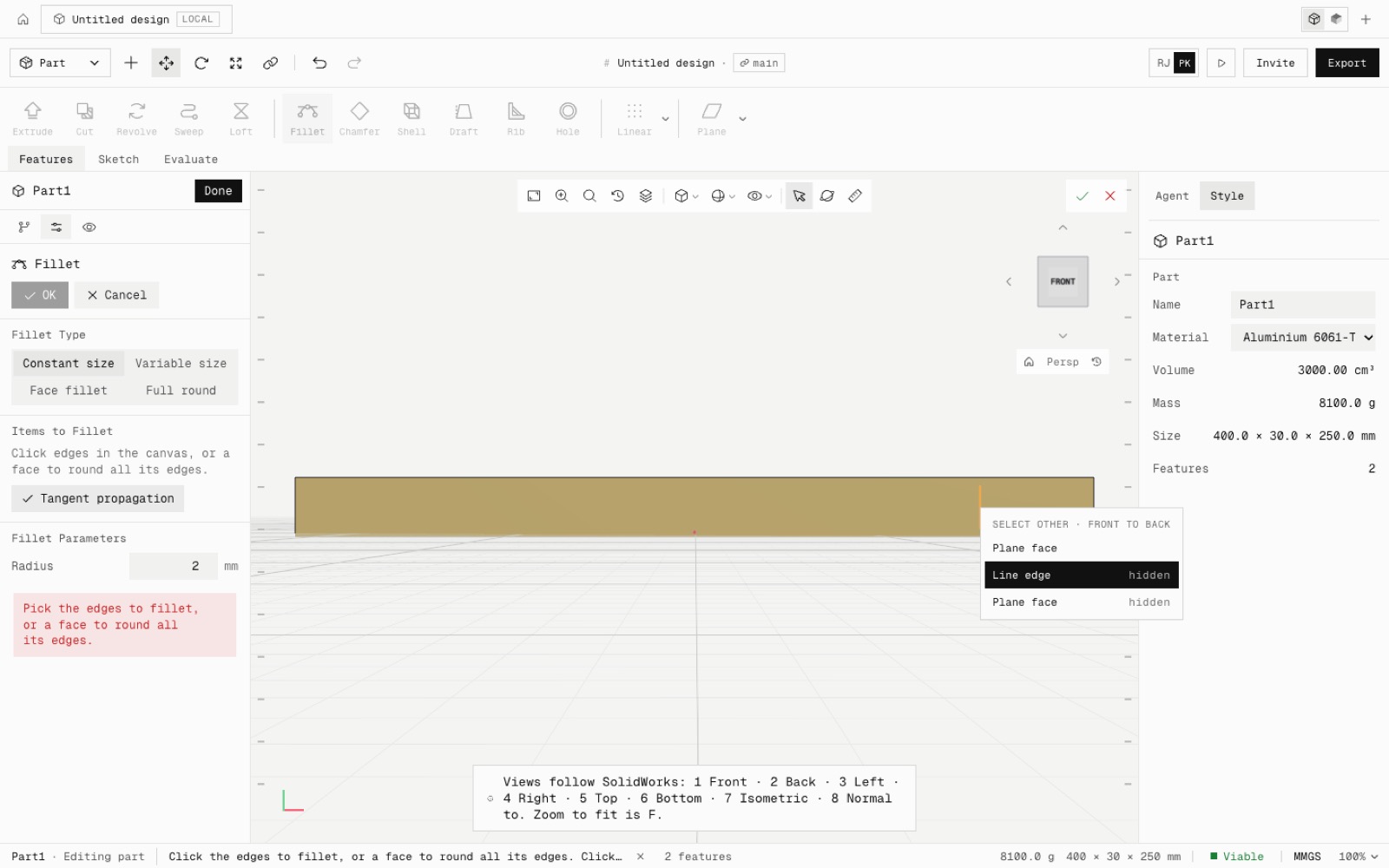
A clean blank part, Zoom to Area, Select Other and steadier zoom

Clearing a design now leaves a truly blank Untitled design, with no old title block, callouts or error badge, and one undo brings everything back. Zoom to fit frames the part, the wheel zooms 11 % a notch, a new sketch opens square to its plane at the right size, and Zoom to Area and Select Other (for hidden faces and edges) are in the view toolbar and the right-click menu.

After: After clearing the drone: before, the old name, error badge and leftovers stayed; after, a clean Untitled design with only the part
Before: After clearing the drone: before, the old name, error badge and leftovers stayed; after, a clean Untitled design with only the part
BeforeAfter
A clean blank part
Select Other listing the faces and edges under the cursor, with a hidden back edge highlighted
Select Other

Select all and Delete clears the product, title block, callouts, figures and name, so the blank part shows only the part, and STEP and drawings use the new name. The new blank part adds no undo step of its own: one undo restores the whole design.

F and Home frame the part's solid, else its sketch, else its planes. The wheel steps 11 % per notch, trackpads scale smoothly, and a new part reads 100 % instead of 939 %. A new sketch turns square to its plane and fits the body: 455 mm across on a 400 mm plate, 100 mm on an empty part.

Zoom to Area: drag a box and the view fills with it; Esc cancels. Select Other: right-click the model to list every face and edge under the cursor, front to back, with hidden ones marked. The wheel or hover highlights each, and a click picks it for Fillet, Shell, Draft, a hole face or a sketch.

Added
  • Zoom to Area
  • Select Other
  • npm run test:viewport2
Improved
  • Clearing a design leaves a clean blank document
  • Zoom to fit frames the part
  • Wheel zoom 11 % per notch
  • New sketches open square to their plane at the right size
  • Zoom readout starts at 100 %
Shipped in
6909d8c
Fixv2.47

Patterns copy features in tree order; Cut opens as Blind; a direction arrow on Extrude

A linear or circular pattern of a boss and its hole built the boss over the hole when the hole was ticked first, so the copies came out solid. Patterns and mirrors now copy features in FeatureManager order. A new Cut opens as Blind, as in SolidWorks, and the Extrude preview shows which way it goes before you press OK.

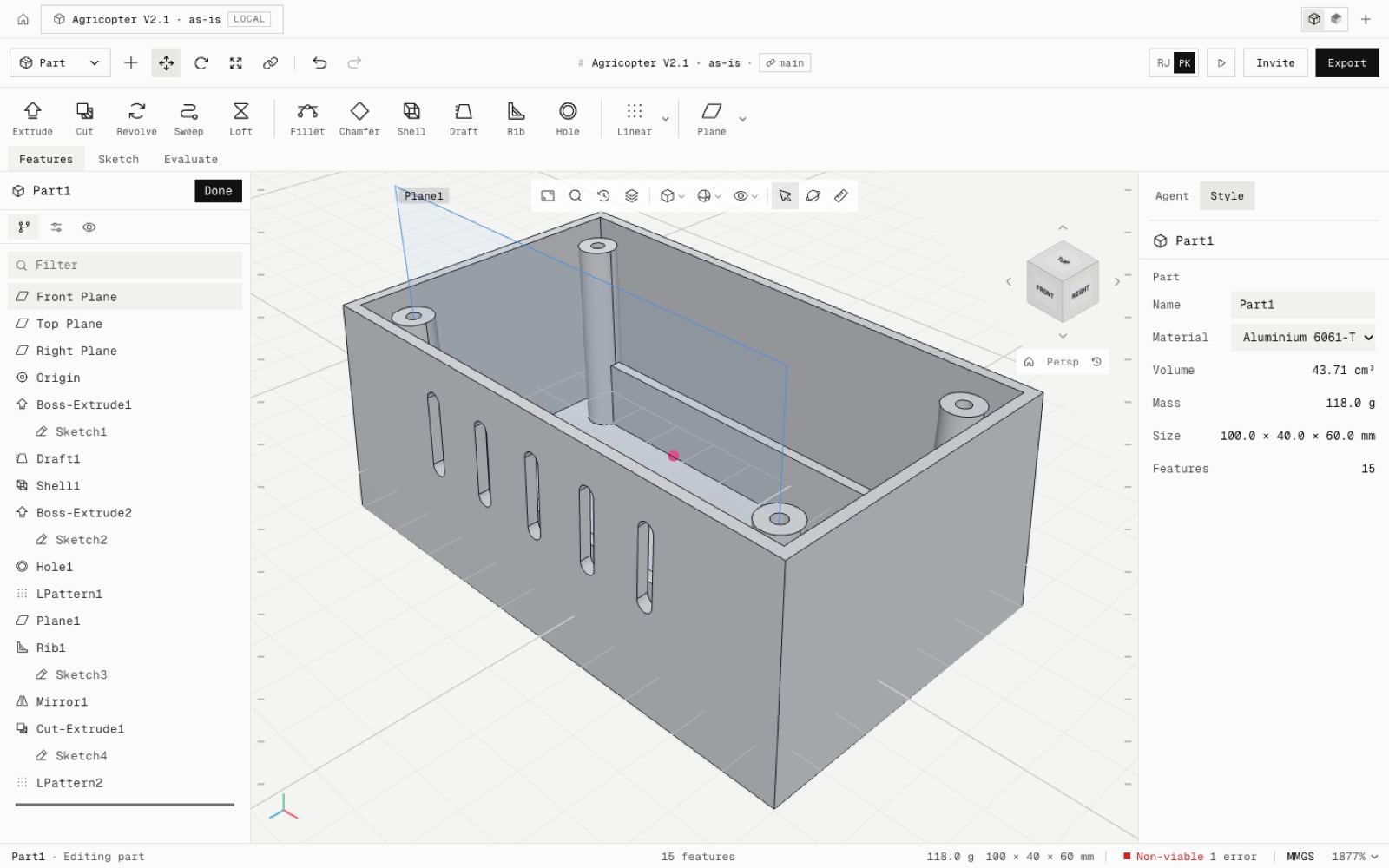
After: The hand-built enclosure before (the patterned bosses stood outside the box, without holes) and after (four bosses with holes inside the shelled box, two ribs, five vents)
Before: The hand-built enclosure before (the patterned bosses stood outside the box, without holes) and after (four bosses with holes inside the shelled box, two ribs, five vents)
BeforeAfter
The electronics enclosure
The Extrude PropertyManager with the blue direction arrow, reversed
Direction arrow
A new Cut opening as Blind 10 mm with a Through All toggle
Cut opens as Blind

Found while building the electronics enclosure by hand. The pattern of its screw bosses had solid tops because the seeds were applied in the order they were ticked. The enclosure now builds to exactly its closed-form volume, 43,711.1 mm³, at 100 × 40 × 60 mm, with every boss and hole at (±40, ±20).

Extruded Cut opens as Blind, at the depth of the last blind cut in the part, or 10 mm. Through All is a toggle under the depth field, one click away.

The Extrude preview draws a blue arrow from the middle of the profile, two for Mid Plane or a second direction. It turns as soon as you click Reverse, and it comes from the same calculation as the solid, so it can never disagree.

Every end condition was checked on the shelled and drafted enclosure, from its inner floor and against its slanted walls, both ways: 43 cases, all matching their closed-form volumes.

Added
  • npm run test:extrude-ends2 (43 end-condition cases on a shelled, drafted body)
Improved
  • Cut defaults to Blind with the last depth
  • Extrude shows its direction before OK
Fixed
  • Patterns and mirrors applied seeds in tick order, not tree order
Shipped in
4b0111c
Featurev2.46

FeatureManager right-click menu, delete that asks first, and a safer Esc

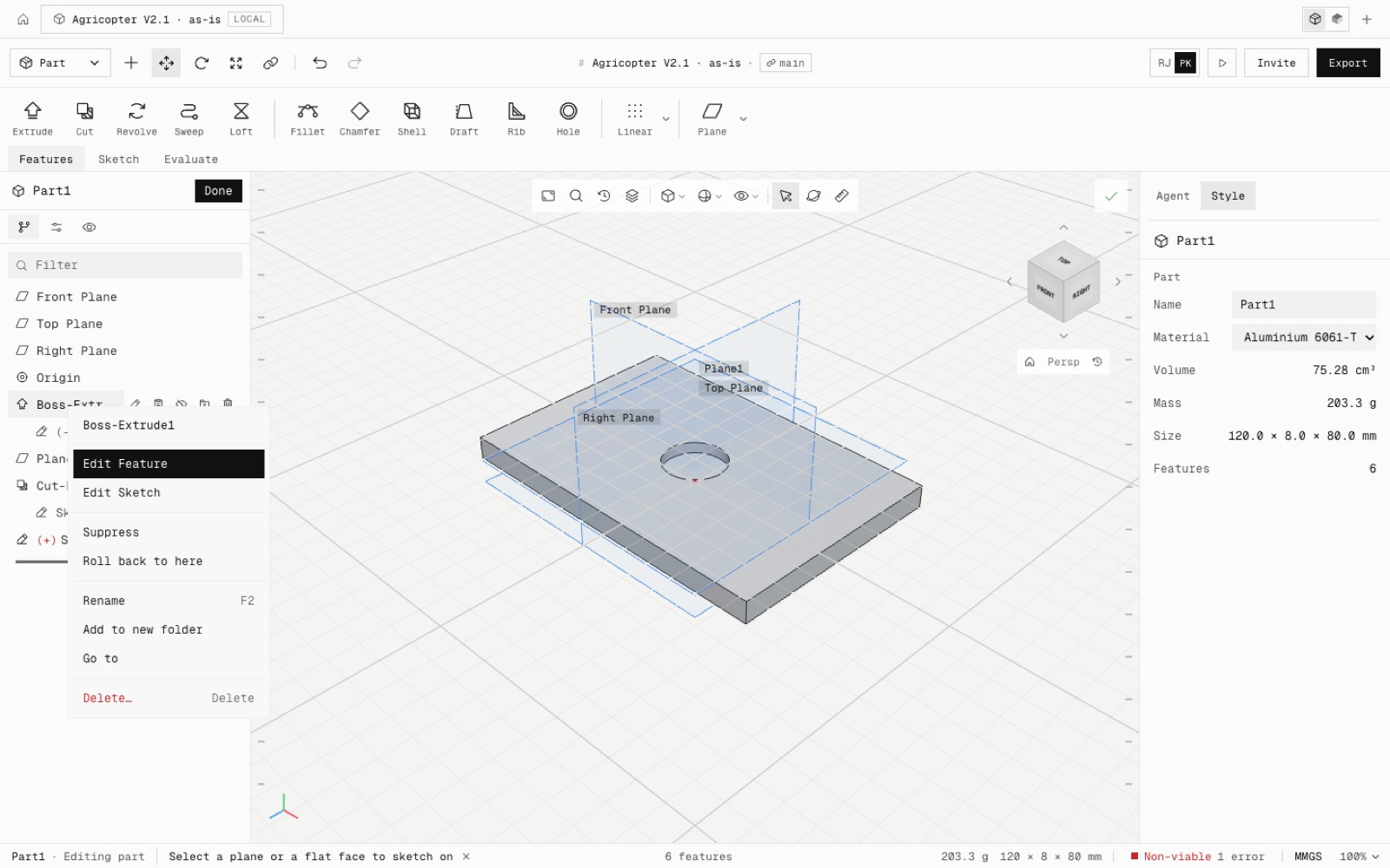
Every FeatureManager row has a right-click menu: Edit Feature, Edit Sketch, Suppress, Roll back to here, Rename, Add to new folder, Go to and Delete. Deleting something others are built on asks first and lists what goes with it. Esc steps back one level at a time and never closes the part.

After: Right-clicking a feature in the FeatureManager: before, nothing; after, the menu with Edit Feature, Edit Sketch, Suppress, Roll back to here, Rename, Add to new folder, Go to and Delete
Before: Right-clicking a feature in the FeatureManager: before, nothing; after, the menu with Edit Feature, Edit Sketch, Suppress, Roll back to here, Rename, Add to new folder, Go to and Delete
BeforeAfter
Right-click a feature
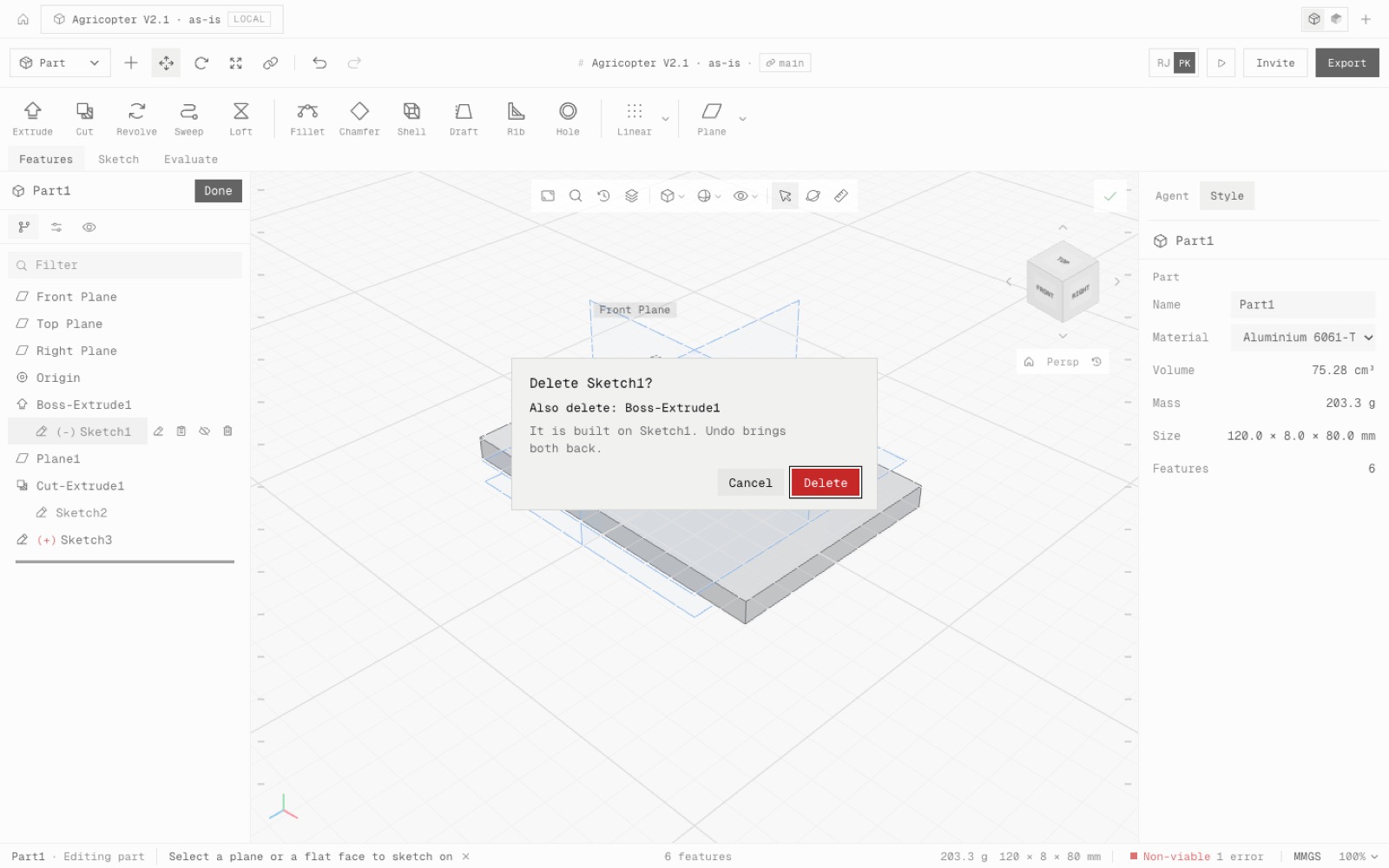
Delete on a sketch with an extrude built on it: the dialog lists what will also be deleted
Delete asks first

The menu works on features, the sketches nested under them, the Front, Top and Right planes, folders and the rollback bar. It opens with a right-click, Shift+F10 or the menu key, and the arrow keys, Enter and Esc move through it. Items that cannot run now show grey with the reason. Each one is a single undo step.

Delete asks first when other features depend on the one you picked, for example "Also delete: Sketch2, Cut-Extrude1". With nothing depending on it, it deletes at once. The Delete key, the row button, the menu and the Delete command all ask.

Esc closes the menu, then cancels the PropertyManager, then leaves the sketch (keeping it), then clears the prompt and the pick. It never closes the part: Done does, or the new Exit part tick in the corner of the view.

Sketch rows show (-) when under defined and (+) when over defined, as in SolidWorks.

Fixed: with a part open and nothing picked, Delete or Backspace deleted the whole part.

Added
  • FeatureManager right-click menu
  • Delete confirmation listing dependents
  • (-) and (+) sketch marks
  • Exit part tick in the confirmation corner
  • npm run test:tree-menu
Fixed
  • Delete with nothing picked deleted the open part
  • Esc with nothing to cancel closed the part
Shipped in
6a03b04
Featurev2.45

Centerline, ⌀ dimensions across it, and horizontal and vertical dimensions

The Sketch tab has a Centerline tool, Smart Dimension gives a ⌀ diameter when you place the label across a centerline, and dragging a dimension's label above, below or beside two points picks horizontal, vertical or aligned, as in SolidWorks. A turned profile can now be fully defined the way engineers dimension it.

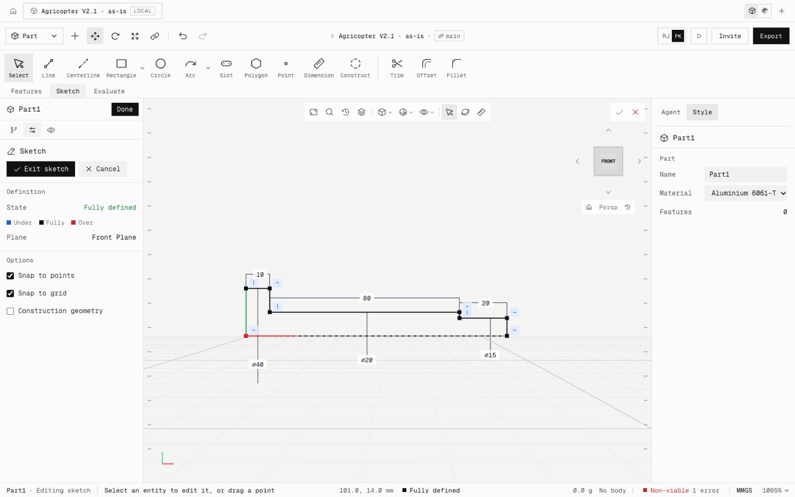
After: The Sketch tab before (no Centerline) and after: the flanged shaft profile with a centerline and ⌀40, ⌀20, ⌀15 dimensions, fully defined
Before: The Sketch tab before (no Centerline) and after: the flanged shaft profile with a centerline and ⌀40, ⌀20, ⌀15 dimensions, fully defined
BeforeAfter
A turned profile, fully defined
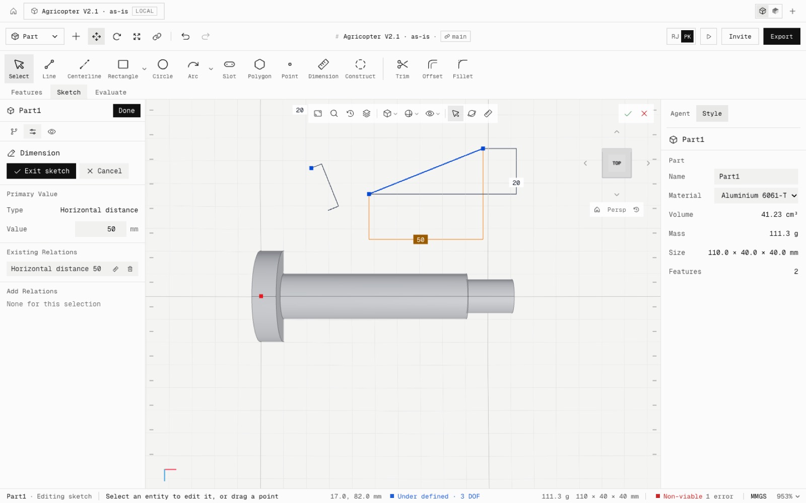
Horizontal 50, vertical 20 and a point-to-line 20 dimension on the Top plane
Horizontal and vertical dimensions

Centerline sits right after Line and draws construction lines with the same horizontal and vertical inference, without switching Construct on and off. Revolve takes it as the axis.

Smart Dimension on a centerline and a line or point gives a diameter when the label goes beyond the centerline, labelled ⌀ and twice the distance. On the item's own side it stays a plain distance. The flanged shaft's profile goes from 6 degrees of freedom to 0 with ⌀40, ⌀20, ⌀15, 10, 80 and 20, and its revolve is exactly π·13,125 mm³.

On two points or an angled line, a label dragged above or below makes a horizontal dimension, left or right a vertical one, and along the line the aligned length. Horizontal and vertical dimensions draw square extension lines, and a preview follows the cursor while you place it.

A clicked dimension shows its type and value in the PropertyManager. Editing it there or on the canvas is one undo step.

Added
  • Centerline tool
  • ⌀ dimensions across a centerline
  • Horizontal, vertical and aligned dimensions by label placement
  • npm run test:sketch-tools2
Shipped in
9e997a1
Featurev2.45

Rivesa R3 runs FE analysis

Ask the agent for an FE analysis and it runs one. It sets up the load cases from your numbers (or uses the defaults for the kind of design), solves them, reads the result like an engineer and paints the stress, displacement or temperature on the canvas when it replies.

After: The same request before (the agent could only run the physics check and pointed at the FEA tab) and after (it ran the FE analysis, gave utilisation and safety factor, and the canvas shows the stress)
Before: The same request before (the agent could only run the physics check and pointed at the FEA tab) and after (it ran the FE analysis, gave utilisation and safety factor, and the canvas shows the stress)
BeforeAfter
Asking the agent for an FE analysis

New tool run_fea: solves the design's load cases with the same FE solver as the FEA tab and reports, per case, the highest-utilised part (stress against its allowable, the utilisation U and the safety factor), the largest displacement and the weakest bolt; the modes and whether the first one is local; the hottest parts; and the findings, with the solver's own idealisation artefacts called out as not failures.

New command set_load_cases: the agent turns your words into load cases. Supports: rests on its base, a free body in flight, or named parts fixed. Loads: accelerations in g, forces on parts, a shock pulse, a temperature soak or steady heat with sun, and modes. It adds to the defaults, replaces them or resets them, and it is one undo step like any other edit.

When it replies, the canvas switches to the shaded view, opens the results and paints the field that tells the story: the worst stress, the largest displacement or the hottest part. The browser solves the final design itself, so the picture matches the design on screen.

The agent runs FE when you ask, or when a requirement is structural (loads, shock, stiffness, heat), after the physics check passes. A case over its allowable sends it back to diagnose and change the design. Its reply carries the utilisation and first mode.

Server side the analysis is screening grade (each part's envelope; fillets, pockets and holes are not modelled) and says so; the FEA tab's B-rep mesh of modelled parts still runs in the browser.

Added
  • run_fea and set_load_cases for the agent
  • The agent opens the FE results on the canvas
  • npm run test:agent-fea
Improved
  • The agent's reply carries FE utilisation and first mode when it ran one
Try it

Open a design, go to the Agent tab and ask: run an FE analysis and show me where the stress is. Or: put 20 N on one arm tip and show the deflection.

Open Speed
Shipped in
9d1e6ad
Fixv2.44

Six modelling fixes from building five real parts by hand

Five parts were built from a blank part using only clicks and keys: a motor mount plate, a flanged shaft, a drafted and shelled enclosure, a lofted duct with a swept handle, and a round of edits. That turned up six modelling bugs, all fixed. The worst: a sketch on a face did not follow the face when the part changed.

The motor mount plate after its thickness was changed from 8 to 12 mm: the pocket, four holes and the bore stay on the top face
A sketch on a face follows the face
The flanged shaft built by hand: revolve, circular pattern of 6 holes, keyway and chamfers
The flanged shaft

Sketches on faces now follow their face. Making the motor mount plate 12 mm instead of 8 used to leave the pocket as a sealed void inside it. The pocket, holes and bore now move up with the top face.

A rib sketched on a reference plane is built on that plane. It used to go to the Front plane, which put the first rib in the wrong place and made the second fail. Ribs can now be mirrored and patterned like extrudes and holes.

Smart Dimension picks a short line when you click its middle, instead of the nearest end point, so the flanged shaft's profile gets all 6 dimensions and is fully defined. It no longer creates a 0 mm dimension between a line and its own end. Delete with a feature selected in the FeatureManager now deletes it.

The five builds took 31 to 95 clicks each, close to an estimate of the same steps in SolidWorks. The findings and the steps still being improved are in docs/research/manual-build-findings.md, and the builds re-run with npm run audit:manual-builds.

Added
  • npm run test:manual-builds
  • npm run audit:manual-builds (the five builds through the UI)
Fixed
  • Sketches on faces did not follow their face after an upstream edit
  • Ribs on reference planes were built on the Front plane
  • Ribs could not be mirrored or patterned
  • Smart Dimension could not pick a short line
  • Smart Dimension made 0 mm dimensions
  • Delete did nothing on a FeatureManager row
Shipped in
f9ef09b
Featurev2.44

Rivesa R3 thinks before it builds

The agent now reads a request the way an engineer does before touching the canvas. It picks how to think about it: a quick edit, a design from a brief, a set of options, a diagnosis, an improvement or a review. For a brief it pins the requirements down first and shows them above its plan, marking each one as something you said, a default it assumed, or a reading to confirm. You can see how it understood you, and redirect it, before it builds.

After: The same drone brief before (a plan of build steps only) and after (Requirement to design, six requirements tagged you said, assumed or to confirm, then the plan)
Before: The same drone brief before (a plan of build steps only) and after (Requirement to design, six requirements tagged you said, assumed or to confirm, then the plan)
BeforeAfter
Agent panel, mid-build

Six thinking frameworks, each with when it fits and a few moves: Direct edit, Requirement to design, Design space, Diagnose, Improve and Red-team review. They are lenses, not scripts: the agent combines them (a brief that asks for three options is a requirement plus a design space) and skips them for small changes, so a quick question never turns into a project.

Requirement to design: pin down every number given, the defaults a working design also needs, and any word that reads two ways; turn the hard ones into budgets that add up (mass, power, accuracy, cost); pick the architecture and know the runner-up; size from first principles and the catalogue; build in subsystems; finish by checking every requirement.

Design space: name the axes that really change a design, make variants that differ on purpose, meet the brief as written first and then improve on it with one clear idea per variant. Diagnose separates symptom from cause, local from global and real physics from a modelling artefact before fixing anything.

Habits for every request: fit the user (numbers and margins for an engineer, plain words and one recommendation for someone new), think in the open but briefly, take a sensible default instead of stalling, and say which numbers are estimates.

The plan now carries the approach and up to 12 requirements, each tagged you said, assumed or to confirm; assumed and to-confirm ones show in amber, and the folded work log counts them. The build order is no longer drone-only: it follows the load path, with drone and gimbal examples. The reply names every assumption the result rests on and any requirement not met.

Checked offline with a scripted model (npm run test:agent-frameworks): the prompt carries every framework, the plan tool cleans what a model sends, the plan reaches the panel, a direct question still runs with no plan, and saved chats keep the requirements.

Added
  • Thinking frameworks for the agent (lib/agent/frameworks.ts)
  • Requirements with stated / assumed / to confirm in the plan
  • npm run test:agent-frameworks
Improved
  • The plan step reads Thinking it through
  • Build order follows the load path for any product, not only drones
  • Replies name the assumptions a result rests on
Try it

Open the Agent tab and give it a brief with numbers, for example: a quadcopter that carries a 1.5 kg camera for 25 minutes and folds into a backpack.

Open Speed
Shipped in
6774d2e
Featurev2.43

The part editor, laid out like SolidWorks

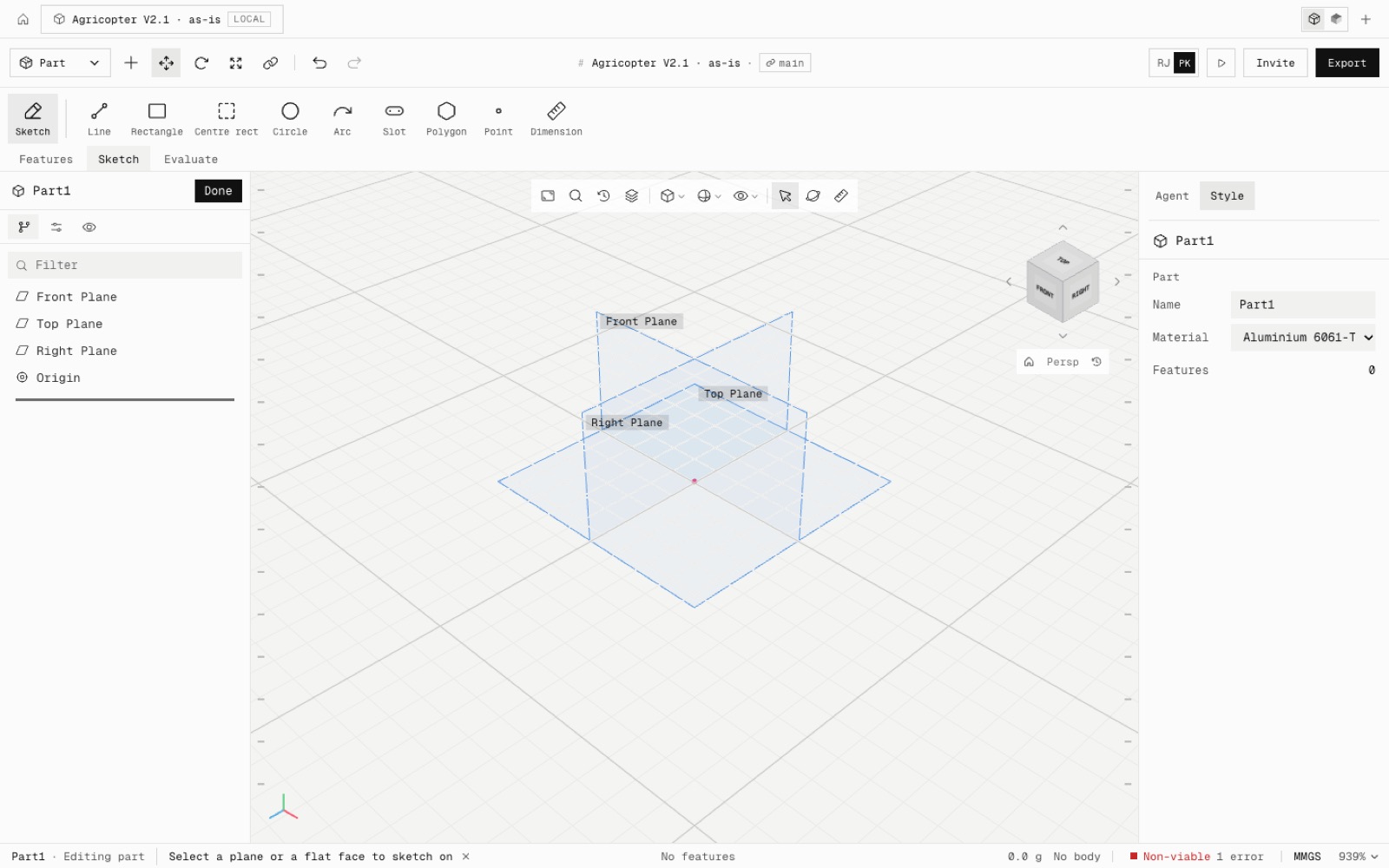
Editing a part now follows the layout SolidWorks users know, finished in our style. The command ribbon sits on top with its tabs underneath, the FeatureManager and PropertyManager are on the left, one view toolbar floats at the top centre of the model, and a status bar runs along the bottom. The sketch panel edits real values instead of showing help text.

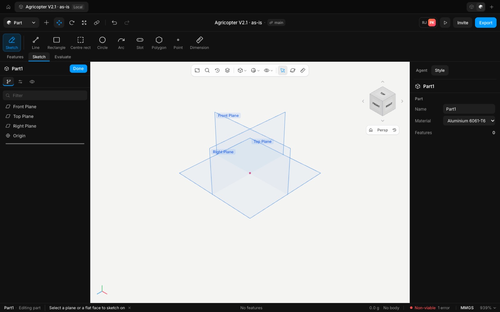
After: A new part before (floating command bar, chips, hint bubble and dock over the canvas) and after (ribbon on top, FeatureManager on the left, view toolbar at the top centre, status bar along the bottom)
Before: A new part before (floating command bar, chips, hint bubble and dock over the canvas) and after (ribbon on top, FeatureManager on the left, view toolbar at the top centre, status bar along the bottom)
BeforeAfter
A new part
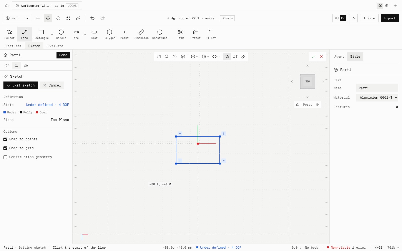
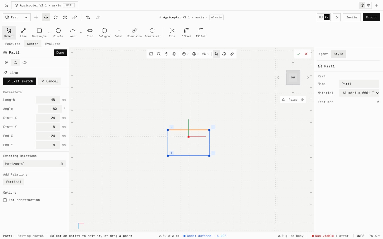
Sketching on the Top plane: the Line PropertyManager with length, angle and end points, existing and add relations, and the status bar reading Under defined · 4 DOF
The sketch PropertyManager
The same new part in the dark theme
dark theme

Laid out from 77 sourced references on how SolidWorks arranges its window (docs/research/solidworks-ui-references.md). Only positions and names were followed: the icons, colours and code are our own.

Ribbon: Features · Sketch · Evaluate tabs under a full-width band of large icon-over-label buttons. Left pane: FeatureManager, PropertyManager and Display tabs, a Filter field, and the tree in SolidWorks' order (Front, Top, Right Plane, Origin, then features). A command or sketch opens its PropertyManager there, with OK / Cancel at the top and in the corner of the view.

The view toolbar runs, left to right: zoom to fit, zoom to selection, previous view, section view, view orientation, display style, hide/show, then select, rotate and measure. The status bar shows the part and what you are editing, one short prompt, the sketch coordinates and definition state (Under defined · 4 DOF), the part's mass and size, viability, MMGS and zoom.

The sketch PropertyManager edits the selection. For a line, edit its length, angle and end points, or for a circle, arc, point or polygon its own values. Existing relations are listed and Add Relations offers only the ones that fit. Typing 60 into a line's length is one sketch undo step.

Gone while a part is open: the floating mass chip, the viability pill, the bottom dock, the help bubbles and the How to and Next lists, and the previous product's title block and callouts. One-pager and Deck move into Export. Other workspaces are unchanged.

Not yet: sketch definition marks in the tree, History and Material folders, Zoom to area, scene and appearance in the view toolbar, and selection breadcrumbs.
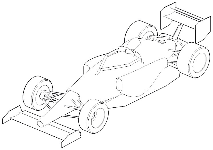
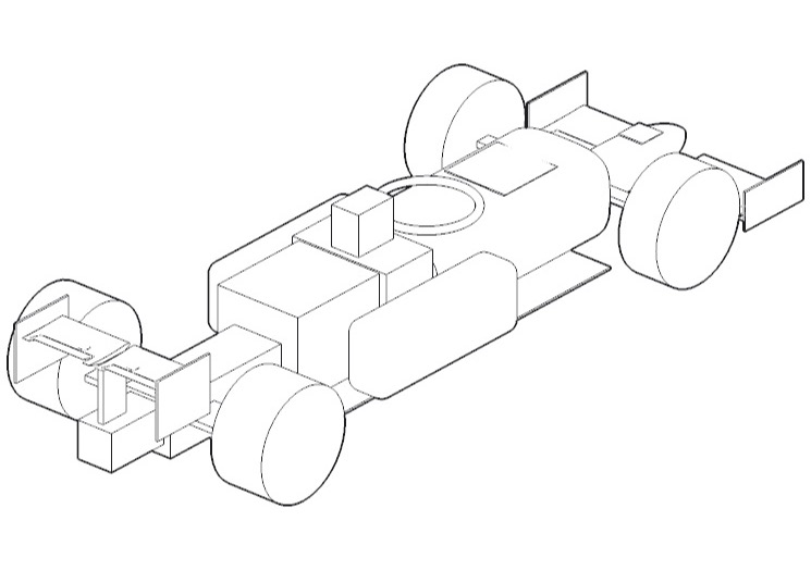
Added
  • Docked command ribbon
  • FeatureManager / PropertyManager / Display tabs and a tree filter
  • Heads-up view toolbar
  • Status bar
  • Sketch PropertyManager with editable values and relations
  • npm run test:part-layout
Improved
  • No help text over the model while editing a part
  • One-pager and Deck are in Export
Try it

Start a new project, pick the Top plane, draw a rectangle and click one of its lines.
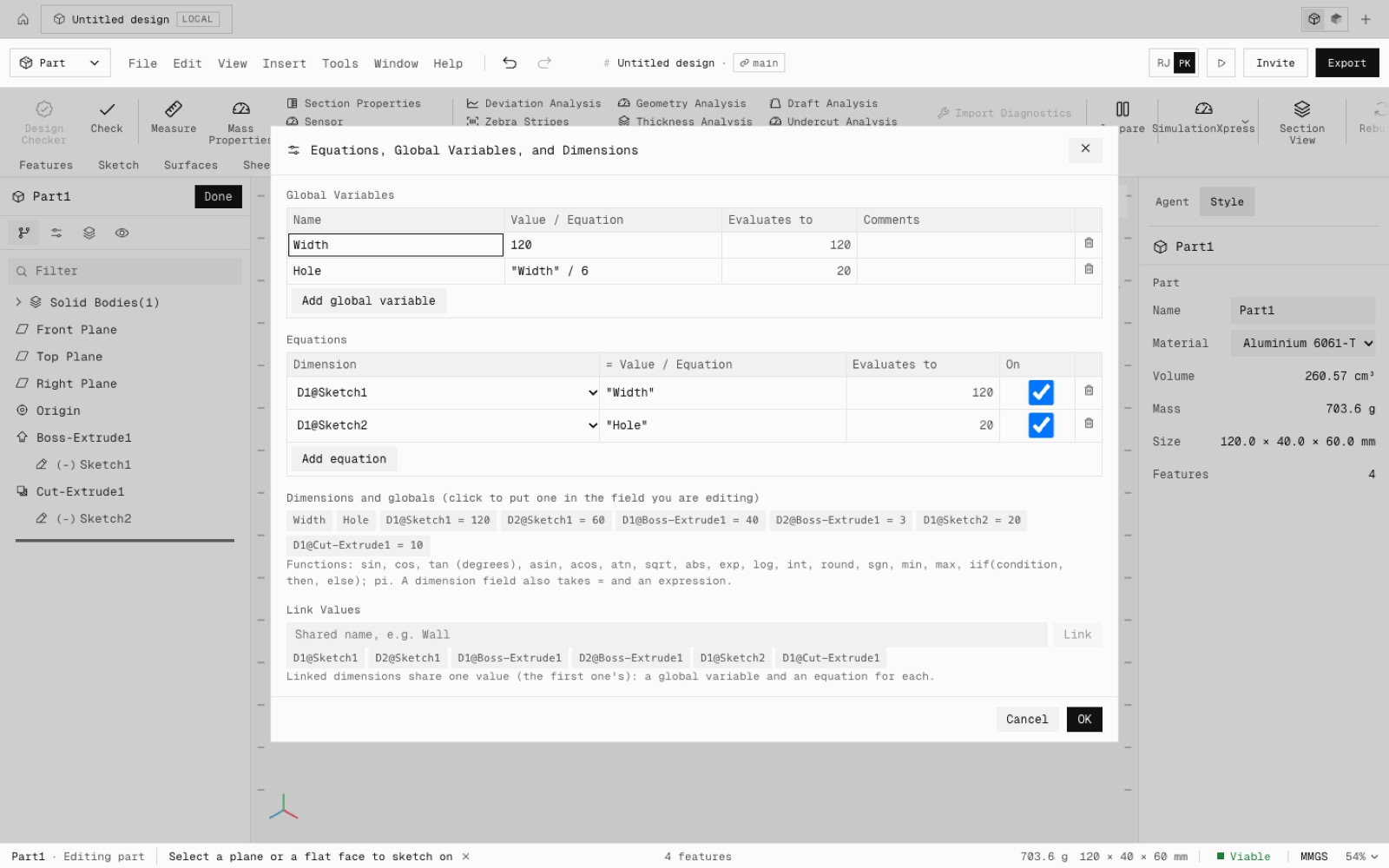
Open Speed
Shipped in
7ddde1a
Featurev2.42

FEA on the real solid

Modelled parts are now analysed on their real OpenCascade solid. They are meshed into 10-node tetrahedra, with smaller elements at holes, fillets and thin walls. Every result says what it was computed on: B-rep solid, or Screening (envelope) for primitives and catalogue parts.
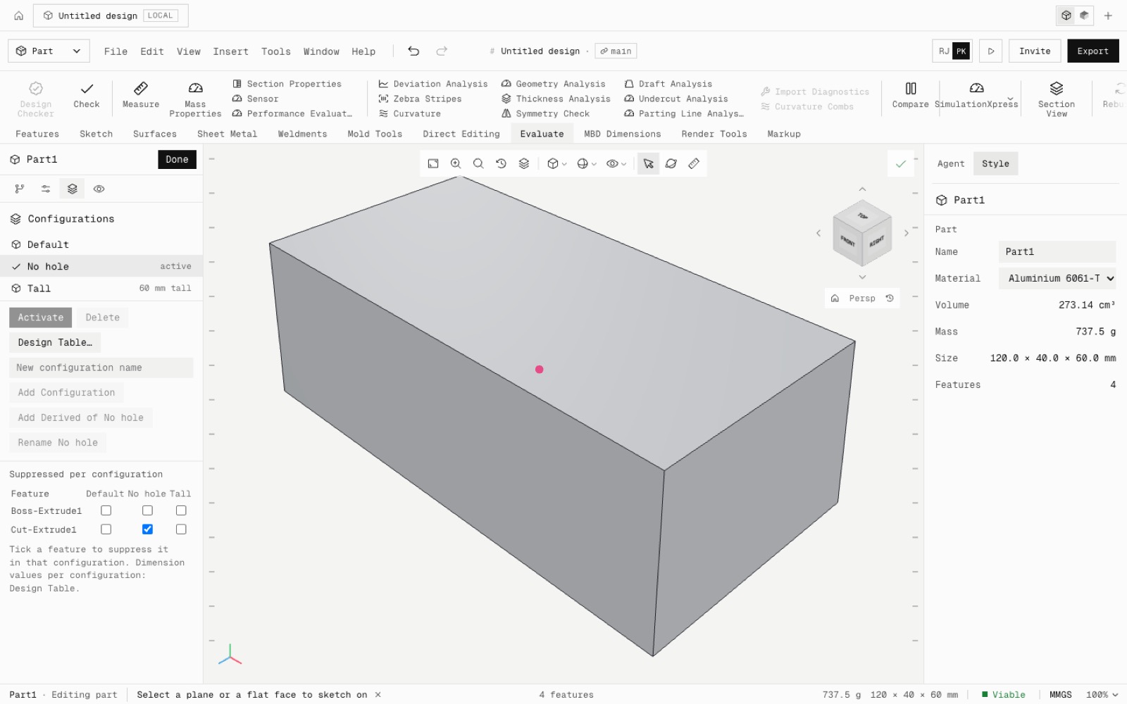
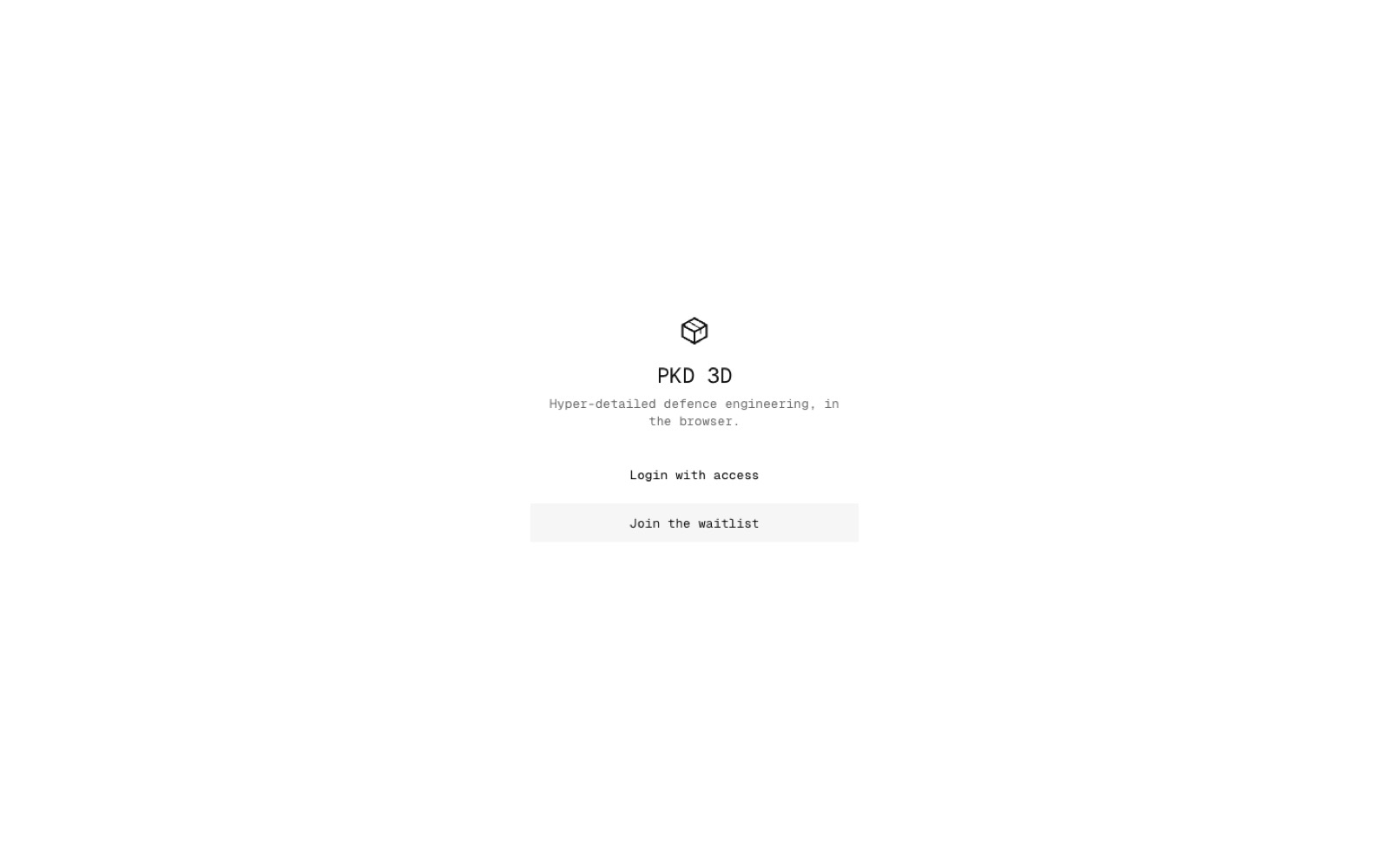
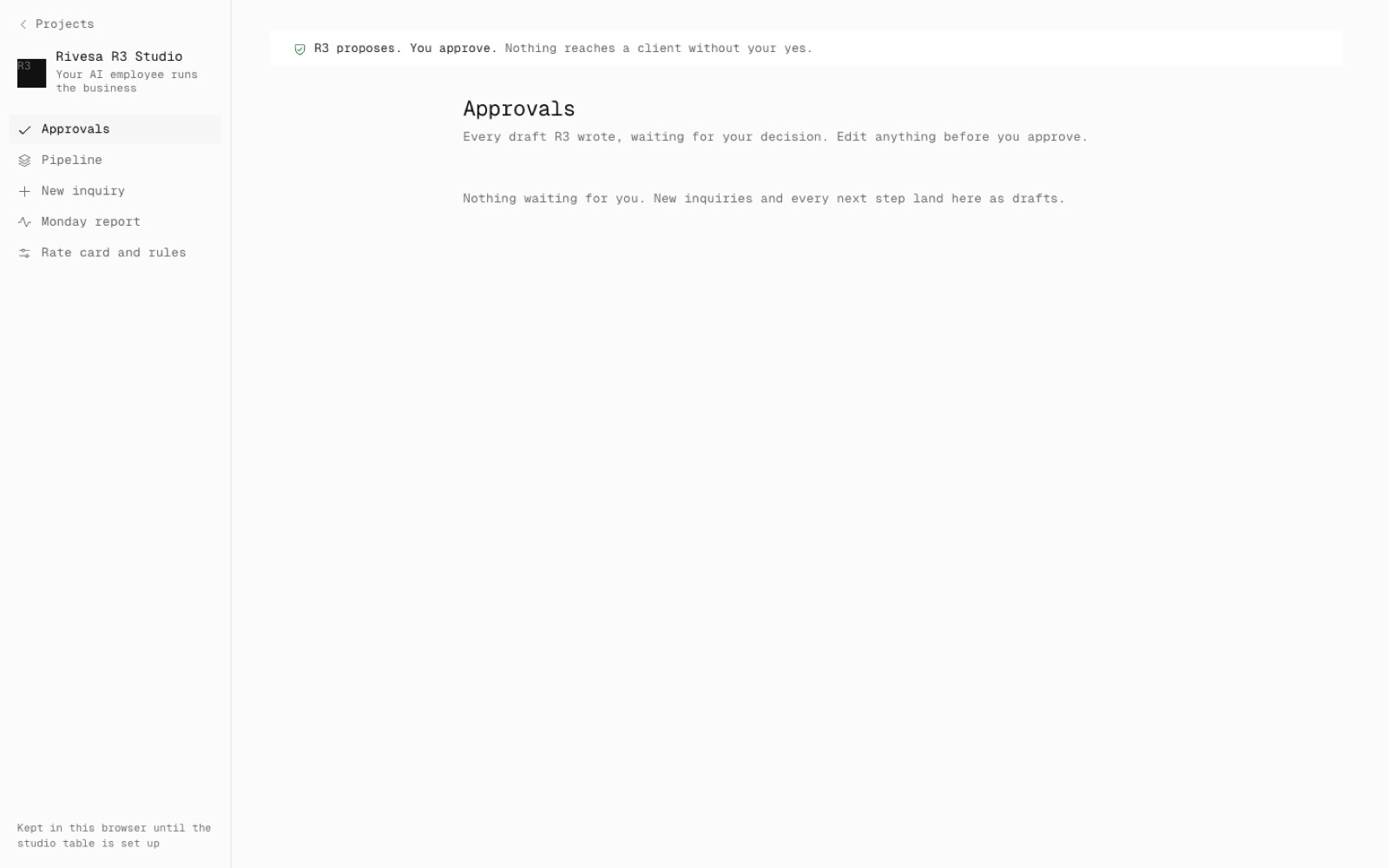
After: The FEA panel on a cantilever: before, the result on the envelope box; after, the same part meshed on its B-rep solid, labelled B-rep solid
Before: The FEA panel on a cantilever: before, the result on the envelope box; after, the same part meshed on its B-rep solid, labelled B-rep solid
BeforeAfter
FEA on the B-rep, labelled
Displacement on the meshed solid: 0.3772 mm tip deflection
Displacement on the solid

This is step N4 of the North Star plan. The FEA worker meshes the kernel's solid of a modelled part and solves it in the same pipeline as before (loads, supports, joints, static and modal). A part that is not modelled still gets the fast envelope model, labelled Screening (envelope), so no envelope result passes for a real one.

Checked against textbook cases on solids built with the app's own features, in the real kernel. Cantilever deflection is within 1% of Timoshenko and bending stress within 2% of M·c/I. A plate with a hole gives Kt 2.45 against Pilkey's 2.506 (0.5% off on a finer mesh). A thick cylinder matches Lamé to 0.07%. The first cantilever mode comes out at 410.8 Hz against 411.3 Hz. A uniform-tension patch test is exact.

The mesh closes the part's skin, every element is valid, and its volume is within 0.2% of the kernel's. Elements are about 4.8× finer at holes and 4.7× finer at R4 fillets than in the core. Meshing takes 0.2 to 5 s in the worker.

Fixed on the way: rebuilding a part's detail geometry shifted the kernel's cached mesh in place, which roughly doubled browser FEA deflections on parts not centred at zero.

Not on solids yet: heat conduction, buckling and shock checks. Stress colours on modelled parts can look streaky, because they are painted onto the display mesh. A few elements under curved faces are flat but valid.

Added
  • Tetrahedral meshing of modelled parts (10-node elements, refined at holes, fillets and thin walls)
  • B-rep solid / Screening (envelope) labels on every result
  • npm run test:fea-brep
Fixed
  • Cached kernel meshes were shifted in place, doubling FEA deflections on off-centre parts
Try it

Model a bracket, open Simulation and run a static case: the result says B-rep solid.

Open Speed
Shipped in
5d18972
Improvementv2.41

R3 Studio moves to its own app

Rivesa R3 Studio (clients, quotes and invoices) now runs as its own app at pkd-r3-studio.vercel.app, and the CAD app no longer ships it. Old /studio links redirect there. Build it with R3 still opens a new project in the CAD app with R3 already working on the brief.

After: Before: R3 Studio inside the CAD app at /studio. After: /studio redirects to the Studio's own app at pkd-r3-studio.vercel.app
Before: Before: R3 Studio inside the CAD app at /studio. After: /studio redirects to the Studio's own app at pkd-r3-studio.vercel.app
BeforeAfter
/studio, before and after

This is step N7 of the North Star plan: one app for CAD, and the studio business tools beside it. The Studio is a separate Next app in apps/pkd-r3-studio with its own Vercel project, and the CAD build no longer compiles or uploads it.

Browser storage and sign-in do not cross from one domain to the other. So Build it with R3 passes the job in the link: the Studio picks the project's id, and the CAD app creates the project in the Studio folder with the client's tag and starts R3 on the brief. Open the design reopens the same project without running R3 again.

The Studio has its own access gate (the same code). Anything saved in the old /studio belongs to the old sign-in, so the new app starts empty.

Added
  • pkd-r3-studio.vercel.app
  • Studio to CAD hand-off links
  • npm run test:studio-split
Improved
  • The CAD app no longer ships Studio code
Try it

Open pkd-defense-3d.vercel.app/studio: it lands on the Studio's own app.

Open Speed
Shipped in
ce8ebac
Featurev2.40

Exact section and detail views, and fasteners drawn as vectors

Section views now cut the real solid and hatch the cut faces at 45°, detail views clip the exact edges, and screws, washers and nuts are drawn from their ISO dimensions. A 5-sheet set of a modelled part has no screenshots left and drafts in about a second instead of 70 to 100.

The section and detail sheet of a base plate: front view with the A-A cutting line, Section A-A with its cut faces hatched at 45° and the hole clear, and Detail B at 5:1
Section A-A and Detail B, exact
Close up of a vector view with two M6 socket screws drawn from their ISO dimensions
Fasteners drawn as vectors

This completes step N5 of the North Star plan. For a section, the kernel worker cuts the solids with the section plane, keeps the side the arrows look at and projects it with hidden-line removal. It also returns the cut faces with their outlines. The sheet hatches them at 45°, 2.8 pt apart on paper at any scale, with holes left clear. In the DXF, the hatch is on its own SECTION layer.

A detail view is the front view's own vector edges, clipped to the detail circle: straight edges become chords and arcs stay exact.

Socket, button, countersunk, hex and set screws, washers and hex and nyloc nuts are built as simple solids from the ISO tables and placed along their axes, exploded moves included. Hole callouts skip screw heads.

Still captured from the canvas: views with bought-in parts that carry detailed geometry (motors and the like) and views of more than 160 solids. Section views also hatch fasteners, where drafting practice leaves bolts uncut.

Added
  • Exact section views with 45° hatching (SECTION layer in DXF)
  • Exact detail views
  • Fasteners in vector views
Improved
  • A 5-sheet set drafts in about 1 s instead of 70 to 100 s
Try it

Open a modelled part, Export → Dimensional drawings → 5 sheets, then look at sheet 4.

Open Speed
Shipped in
6e23b09
Featurev2.39

Exact drawing views: hidden-line vectors, DXF and a true-scale PDF

Drawing views of modelled parts and plain primitives are now drawn from OpenCascade's exact hidden-line projection: visible edges, hidden edges dashed and tangent edges thin, as vectors at true scale. Drawings download as DXF, vector PDF and SVG, and dimensions measure the real edges.

A part sheet for a 160 × 20 × 60 plate with a Ø20 hole and four Ø8 holes: front, top and right views as exact vectors, hidden holes dashed
The part sheet, drawn as exact vectors
Close up: the top view's ⌀20 and 4× ⌀8 callouts, the front view's dashed hidden holes and the 160.00 overall width
Hidden lines and callouts from the B-rep

This is the first part of step N5 of the North Star plan. The kernel worker runs OpenCascade's exact hidden-line removal on the part's solid for each view direction, and returns visible, outline, tangent and hidden edges with circles kept exact. Before this, views were screenshots of the canvas.

Hidden lines are dashed and tangent edges (the seams of fillets) thin. A hole seen end-on gets its ⌀ callout from the real circle, for example ⌀20 and 4× ⌀8 on the test plate. The overall dimensions are measured from the B-rep edges: 160.00, 60.00 and 20.00.

The viewer has a DXF button (LINE, CIRCLE, ARC and LWPOLYLINE on the VISIBLE, HIDDEN and TANGENT layers, in mm at 1:1). PDF now downloads a vector file: on the 34 × 22 in sheet, a 160 mm edge drawn at 2:1 measures 320 mm on paper.

Still raster for now, being finished next: section and detail views, views that show fasteners, bought-in parts with detailed geometry, and views of more than 80 parts. An all-vector 3-sheet set redraws in about 0.4 s.

Added
  • Exact hidden-line views from OpenCascade (HLRBRep)
  • DXF download
  • Vector PDF download at true scale
  • npm run test:drawing-hlr
Improved
  • Driven dimensions measure B-rep edges
  • Hole callouts read the real circle
Try it

Add a modelled part, open Export → Dimensional drawings, then download the DXF.

Open Speed
Shipped in
064fe02
Featurev2.38

One document model: Convert to features

A part is now either a modelled part (a feature history placed in the assembly) or a legacy primitive body. Convert to features turns a box, rounded box, cylinder, tube, capsule, sphere or torus into the sketch and features that build the same solid in the same place. Mass, the parts list and interference read the real B-rep.

After: A box from the Toolbox, before (no conversion) and after (Legacy primitive label and a Convert to features button)
Before: A box from the Toolbox, before (no conversion) and after (Legacy primitive label and a Convert to features button)
BeforeAfter
A primitive is a legacy body
The same box after Convert to features: Edit part, envelope 40 × 20 × 40 mm and the exact mass, 86.4 g
Converted: a modelled part with its exact mass

This is step N3 of the North Star plan. Primitive bodies are now labelled Legacy primitive in Style → Size, and the part card has a Convert to features button. The part keeps its id, joints, material, role and place.

Each shape gets the history an engineer would draw. A box is a centred rectangle on the Top plane extruded mid-plane, and a rounded box adds a fillet on all 12 edges. A cylinder is a circle, and a tube two circles. A sphere, capsule or torus is a revolved profile. OpenCascade builds each one to the primitive's closed-form volume and box.

Once the kernel answers, the converted part's envelope and mass come from the solid. A 40 × 20 × 40 aluminium box reads 86.4 g. The drawings' parts list sums the same mass, and Interference detection intersects the B-rep.

Detailed parts, catalogue parts and parts with a datasheet mass keep their bodies. Converting them would replace that mass, so the command says so. The agent has the same command (convert_to_features).

Added
  • Convert to features (part card, Quick actions, agent)
  • Legacy primitive label on primitive bodies
  • npm run test:one-model
Improved
  • A converted part fits its envelope and mass to its solid
Try it

Add a Box from the Toolbox, click Convert to features, then Edit part.

Open Speed
Shipped in
49ace9b
Featurev2.37

Workspaces: Part, Assembly, Drawing, Simulation, then add-ins

The workspace switcher now puts the four CAD workspaces first: Part, Assembly, Drawing and Simulation. Wiring, Teardown and Render move to an Add-ins group below. Each workspace loads only when you first open it, and the Agent tab works in every one.

After: The workspace switcher before (Canvas, Wiring, FEA, Teardown, Render) and after (Part, Assembly, Drawing, Simulation, then Add-ins: Wiring, Teardown, Render)
Before: The workspace switcher before (Canvas, Wiring, FEA, Teardown, Render) and after (Part, Assembly, Drawing, Simulation, then Add-ins: Wiring, Teardown, Render)
BeforeAfter
The workspace switcher
The Agent tab open beside the Simulation workspace
The agent in every workspace

This is step N6 of the North Star plan. Part is the old Canvas workspace and Simulation the old FEA one. Their ids and shortcuts are unchanged, so ⌥1 and ⌥3 still work.

Assembly (⌥9) is new. It lists the components, shows each mate as met or not met, sums up the last interference check, and has Mate, Interference and Explode / Collapse in one place. Mating now opens Assembly.

Drawing (⌥0) is new. It drafts the one-pager, the deck or 3 to 10 sheets, reopens the last set, and draws the teardown illustration.

Each workspace panel is its own chunk, fetched the first time you open it, with a small loading state. The Agent panel stays mounted beside every workspace, so a reply in progress, its Stop button and the scroll position survive a switch.

Known limits: Part is the default workspace, so it still loads on first paint. Opening the Agent tab during a Simulation run stops the run, as before. While the drawing sheets are open they cover the sidebar.

Added
  • Assembly workspace (⌥9)
  • Drawing workspace (⌥0)
  • Add-ins group in the switcher
  • npm run test:workspaces
Improved
  • Workspace panels load on first open
  • The Agent tab works and keeps its state in every workspace
Try it

Open the switcher at the top left, pick Assembly, then open the Agent tab.

Open Speed
Shipped in
e716fd1
Improvementv2.36

The agent uses the same commands you do

Every agent tool that changes the design is now the agent's form of a command: 22 part-modelling commands and 11 assembly commands. Sweep, loft, draft, rib, reference planes and axes, suppress, rename, rollback and mates are new to the agent. A part the agent builds has the same feature tree as one built by hand.

Before: 22 tools that change the design, 11 of them hand-written assembly tools. After: 38 tools, 6 read-only and 32 generated from 33 commands
The agent's tools, before and after

This is step N2 of the North Star plan. The agent's tool list is now generated from the command layer, plus a few tools that only read (the design, the catalogue, the feature list, the physics check). No tool edits the design on the side.

Adding a part, moving, grouping, swapping in a catalogue part, callouts and renaming are now assembly commands with their own schemas. Sketch, extrude, fillet, holes, patterns, mirror and delete keep the agent's smart edge and face pickers, but every change still goes through the part-modelling command, with the same checks the PropertyManager uses.

Checked without a live model: a scripted agent sketches an 80 × 40 rectangle, extrudes it 20 mm, fillets the four corners 2 mm and drills four M6 holes. Its feature tree matches the one built through the editor's commands, and both solids build in OpenCascade to the same volume, 61,194.372 mm³.

Added
  • Agent tools for sweep, loft, draft, rib, reference planes and axes, suppress, rename, rollback and mates
  • npm run test:agent-commands
Improved
  • Agent deletes go through the Delete command and keep FeatureManager folders
Try it

Open the Agent tab and ask: sketch a rectangle 80 × 40, extrude it 20 mm, fillet the edges 2 mm and add four M6 holes.

Open Speed
Shipped in
941388c
Improvementv2.35

One command layer for modelling

Every modelling change, from a sketch, extrude or fillet to a hole, pattern, mirror, reference plane or axis, a delete, suppress, rename or rollback, and a mate, is now one named command. The PropertyManager, the sketch editor, the FeatureManager and the Mate tool all commit through it, and each command is one undo step.

After: Quick actions with extrude typed: before, nothing matches; after, Extruded Boss/Base, Extruded Cut and the patterns are listed
Before: Quick actions with extrude typed: before, nothing matches; after, Extruded Boss/Base, Extruded Cut and the patterns are listed
BeforeAfter
Quick actions finds the modelling commands

This is step N1 of the North Star plan: before this, the panels wrote straight into a part's history. Now each change goes through one named command with a parameter schema and its own checks, so a bad input is refused with a reason and nothing is half-applied.

The commands are also in Quick actions (⌘K / Ctrl+K) and Settings → Commands, under a new Model category. Type extrude, fillet or hole to open that feature's PropertyManager on the part you are editing.

If OK is refused, the PropertyManager stays open with the reason (for example a sketch that no longer exists) instead of closing and losing your input.

The same commands are what the in-app agent will use next (N2), so a part built by the agent and a part built by hand get the same feature tree.

Added
  • 21 Model commands in Quick actions and Settings → Commands
  • npm run test:model-commands
Improved
  • A refused PropertyManager OK keeps the panel open and says why
  • Delete, suppress, rename and rollback are one undo step each, through the same commands
Try it

Click New part, then press ⌘K and type extrude.

Open Speed
Shipped in
b8b0d41
Featurev2.34

SolidWorks wave 1: sketch tools, draft, rib, reference geometry, interference, section views

Five more SolidWorks commands land together. The sketch gains Slot, Polygon, Tangent arc, Trim, Offset and Sketch fillet. Parts gain Draft, Rib, and reference planes and axes. Assemblies get Interference detection, and drawings get Section and Detail views.

After: The Sketch tab before and after, with a slot, hexagon, filleted rectangle and offset
Before: The Sketch tab before and after, with a slot, hexagon, filleted rectangle and offset
BeforeAfter
Sketch tools
After: The Features tab before and after, with Draft, Rib and reference geometry, on a boss built on a 30° plane
Before: The Features tab before and after, with Draft, Rib and reference geometry, on a boss built on a 30° plane
BeforeAfter
Features and reference planes
A block with its four sides drafted 5°
Draft
A rib across a U channel
Rib
After: The BOSS pedestal before and after running Interference detection
Before: The BOSS pedestal before and after running Interference detection
BeforeAfter
Interference detection
The deck's Section and detail views sheet
Section A-A and Detail B

Sketch: straight slots, polygons (6 sides by default) and tangent arcs (press A while drawing lines). Trim cuts a piece back to its nearest crossings. Offset copies a chain at a distance driven by one dimension. Sketch fillet rounds a corner and trims both lines. Each adds the relations SolidWorks adds, so the degrees of freedom stay right.

Features: Draft tapers faces about a neutral plane (a 40 × 40 × 20 block at 5° comes out at the exact frustum, 29,282 mm³). Rib makes a wall from an open sketch line and extends it until it meets the part.

Reference geometry: planes offset from, at an angle to, through 3 points of, or parallel to existing geometry, and axes through two points, along an edge, down a cylinder or where two planes meet. They follow upstream edits, you can sketch on the planes, and Revolve, Circular pattern and Mirror can use them.

Interference detection (Shift+I, or Interference in the dock) checks every visible part against every other with exact solid intersections. It lists each pair that shares volume, largest first, and draws the overlap in red. Coincident faces count as touching, and fasteners and hidden parts can be left out.

Drawings: decks and sets of 5 or more sheets get a sheet with Section A-A (cutting line with arrows, cut faces hatched at 45°) and a circled Detail B at 2:1 or more. The deck grows to 11 sheets so nothing is dropped.

To keep the bars to one row, related commands share flyouts as in SolidWorks: Rectangle, Arc, Patterns and Reference geometry. Exit sketch and Cancel are in the PropertyManager.

Added
  • Slot, Polygon, Tangent arc, Trim, Offset, Sketch fillet
  • Draft and Rib
  • Reference planes and axes
  • Interference detection
  • Section and detail views on drawings
Improved
  • Flyouts keep the command bars to one row
  • Sketches open framed on their geometry
  • Darker section hatching
Try it

Open a new project, sketch a rectangle on the Top Plane, then try Fillet and Offset on the Sketch tab.

Open Speed
Shipped in
368fd80fc9635d5a9b8fa9709706b710a1dd13d1cf
Featurev2.33

Teardown illustration

Export → Teardown illustration draws the open design as an exploded technical illustration: fine ink on near-white paper, light grey parts, part names at the edges of the sheet. The assembled view is one switch away, and it downloads as SVG, PNG or PDF.

After: Before: the Export menu with dimensional drawings, STEP, STL and JSON. After: the BOSS pan-tilt pedestal as an exploded technical illustration, part names in columns at the sheet edges
Before: Before: the Export menu with dimensional drawings, STEP, STL and JSON. After: the BOSS pan-tilt pedestal as an exploded technical illustration, part names in columns at the sheet edges
BeforeAfter
Export → Teardown illustration: the BOSS pedestal, exploded
The same BOSS illustration in the assembled view, with fewer labels because more parts are hidden
Assembled, one switch away
The BOSS exploded illustration in the dark theme: the same drawing, labels in sentence-case sans
dark theme: labels in its sans
The Agricopter V2.1 exploded: arms, motors, props, tank and landing gear apart, screws backed out of their holes
Agricopter V2.1, exploded

Built on Jakub Krehel's teardown skill. Every part and fastener is drawn from the same geometry as the canvas, through a parallel axonometric camera with hidden lines removed. The parts come apart along the editor's own split-up plan, and each screw backs out of its hole along a dashed trail.

Part names sit in two columns at the left and right edges of the sheet, each with a hairline leader to its part, so no label covers the drawing. Repeated parts share one label with a count (Motor ×6), and each leader starts at the point of its part where it crosses the fewest lines. Hover a label to ink its part in blue, or switch Labels off.

In the Tech theme the labels are small uppercase monospace. In the dark theme they are set in its sans, as the names are written. The drawing is the same in both.

The SVG carries the app's fonts inside the file, the PNG is 300 dpi at A3, and the PDF is a vector A3 page. The BOSS pedestal draws in about five seconds, in the background.

Added
  • Export → Teardown illustration (also File menu, Quick actions and Alt+8)
  • SVG, 300 dpi PNG and vector PDF downloads
  • npm run test:illustration
Try it

Open the BOSS pan-tilt pedestal, click Export → Teardown illustration, then switch between Exploded and Assembled.

Open Speed
Shipped in
eefd9db
Featurev2.32

CommandManager: Features, Sketch and Evaluate

The part modeller's commands sit in SolidWorks-style tabs, and the new Evaluate tab measures, sections and gives the mass properties of the part you are editing.

After: A new part's command bar before (one flat row) and after (Features, Sketch and Evaluate tabs)
Before: A new part's command bar before (one flat row) and after (Features, Sketch and Evaluate tabs)
BeforeAfter
The CommandManager tabs
The Evaluate tab with Mass properties open on a plate with a hole
Evaluate → Mass properties

Above the canvas, the command bar now has three tabs, as in SolidWorks' CommandManager:

• Features: extrude, cut, revolve, sweep, loft, fillet, chamfer, shell, hole, patterns and mirror.

• Sketch: open a sketch, or pick a plane and go straight to a line, rectangle, circle, arc or dimension. While a sketch is open this tab shows its tools.

• Evaluate: Measure, Mass properties, Section view and Rebuild.

A new part opens on the Sketch tab, since its first step is a sketch.

Mass properties lists the material, density, volume, mass and bounding box of the part. For a 100 × 60 × 10 mm aluminium plate with a 20 mm hole it reads 56,858 mm³ and 153.5 g, exactly the hand calculation.

Fixed: the zoom read-out on a new blank part said 1 %. It now reads 100 % at the default view.

Added
  • CommandManager tabs
  • Evaluate: Measure, Mass properties, Section view, Rebuild
Fixed
  • Zoom read-out of 1 % on a blank part
Try it

Click New project, then the Evaluate tab once you have extruded a sketch.

Open Speed
Shipped in
eed3813
Improvementv2.31

One platform: CAD first, the agent on top

No more choosing between Manual and R3. A new design opens as a blank part with its origin and three planes, like a new SolidWorks part. The design tree leads the left panel, and the agent works beside you in the right panel.

After: A blank design before (prompt cards) and after (Part1 with its planes)
Before: A blank design before (prompt cards) and after (Part1 with its planes)
BeforeAfter
A blank design is a blank part
After: The projects page before, with the Manual or R3 chooser, and after
Before: The projects page before, with the Manual or R3 chooser, and after
BeforeAfter
New project: no chooser
After: The left panel before (Designs) and after (Design tree first)
Before: The left panel before (Designs) and after (Design tree first)
BeforeAfter
Design tree, Library, Toolbox
After: The drawing viewer before, asking for sheets on a one-pager, and after
Before: The drawing viewer before, asking for sheets on a one-pager, and after
BeforeAfter
One-pager: no sheet count
Sketching on the Top Plane of a new part
Sketch on Top Plane

New project opens a blank design straight away. A blank design opens as Part1 with its Origin and Front, Top and Right planes in the design tree: pick a plane and sketch. The canvas no longer shows prompt cards or a separate Model it yourself button. Ask the agent in the right panel to build, fix or draft at any point, on the same design.

The left panel follows SolidWorks. Design tree, the FeatureManager rooted at the design's name, comes first and is open by default. Library holds the products, templates, physics laws and materials. Toolbox holds primitives and catalogue components.

A one-pager is one sheet, so it no longer asks how many. A deck still offers 3, 5, 7 or 10 sheets.

The Tech theme is softer on the eye. Whatever is selected is a light grey instead of a black box, and menus, dialogs and the dock have hairline edges. The ticks down the canvas edges are lighter.

Fixed: the New project button text was invisible (black on black), Exit sketch wrapped onto two lines, and drafting an empty design now says to extrude or revolve a sketch first.

Improved
  • One platform instead of Manual and R3 modes
  • Design tree first in the left panel
  • Softer selection in the Tech theme
  • One-pager without a sheet count
Fixed
  • Invisible New project button text
  • Exit sketch wrapping
  • Empty-design drawing message
Try it

Click New project on the projects page, then double-click Top Plane in the design tree to start sketching.

Open Speed
Shipped in
5ba7ec5
Improvementv2.30

Interfaces skills, loading.dev loaders, readable Tech greys

Jakub Krehel's open-source interface skills now ship with the project, his loading-dev indicators replace our spinners, and the Tech theme passes contrast without losing its sheet look.

After: The Tech editor before and after the contrast pass
Before: The Tech editor before and after the contrast pass
BeforeAfter
Counts, units, inactive tabs and the search field now read clearly
The drawing viewer drafting a deck with the Blocks loader
Drafting a deck: loading-dev's Blocks

Sixteen of Jakub Krehel's MIT-licensed agent skills (github.com/jakubkrehel) are installed for the project, including better-interface, better-colors, better-accessibility, better-typography, interface-review, teardown and make-interfaces-feel-better. Every agent working on PKD 3D can now use them.

Loaders are his loading-dev library: an orbit beside each of the agent's running steps, the classic twelve bars in the build log, and sweeping blocks while a drawing set drafts. They stop moving when the system asks for reduced motion.

Running the colour and accessibility skills over the Tech theme found grey text at 2.6:1. The faintest text is now 5:1, secondary text is 7.5:1, and text fields have an edge you can see (3.2:1). The ## and # marks stay pale because they are decoration, and screen readers skip them.

Headings are balanced and longer text wraps without leaving a single word on the last line.

Added
  • Jakub Krehel's interface skills in .claude/skills
  • loading-dev loaders
Improved
  • Tech theme text contrast (AA)
  • Visible text-field edges
  • Balanced headings, pretty-wrapped prose
Shipped in
aef417734450d4
Featurev2.29

Tech theme

The whole app now reads like a technical sheet: paper and ink, one monospace, square hairline boxes, ## headings and a leader line from every label to its value. The dark dark look stays one click away.

After: The editor in the dark theme (before) and the Tech theme (after)
Before: The editor in the dark theme (before) and the Tech theme (after)
BeforeAfter
Editor: ## heads, leaders, ink selection, ticks on the canvas edge
After: Settings before, and after with the Theme cards
Before: Settings before, and after with the Theme cards
BeforeAfter
Settings → General: pick Tech or the dark interface
After: The projects dashboard before and after
Before: The projects dashboard before and after
BeforeAfter
Projects: the same sheet language

Tech is the new default, after the Interfaces scorecard and Jakub Krehel's /teardown illustrations:

• One monospace at one weight, with hierarchy from ink against grey instead of size and bold.

• Square hairline boxes for buttons and fields. Whatever is selected is a solid ink box: a tab, a layer, a segment, a menu item.

• Section heads read "## Payload". A thin leader runs from each label to its value, so "Payload —— 35 kg" scans like a parts list.

• Tick marks run down both edges of the canvas. Callouts are small uppercase labels and dimension lines are ink.

• No shadows, no rounding, no blue: colour is kept for state (viable green, error red).

It covers every page: the editor, Settings, project settings, the projects dashboard, Studio, this changelog and sign-in.

Switch themes from the two logos in the tab bar (the line-drawn cube is Tech, the shaded cube is the dark interface), from Settings → General, from the workspace menu, or with ⌃⌘T (Alt+T on Windows). The choice is saved on this device and applied before the first paint, so pages never flash the other look.

Loading indicators are now monochrome: an orbit for the agent's steps, twelve bars in the build log and a ring of pixels while drawings draft.

Added
  • Tech theme, the default
  • Theme switch in the tab bar, Settings and the workspace menu (⌃⌘T / Alt+T)
  • Monochrome loaders
Improved
  • Labels: one size, leader lines from label to value, quieter icons
  • dark theme kept exactly as it was
Try it

Click the shaded cube at the right of the tab bar to go back to the dark interface, and the line-drawn cube for Tech.

Open Speed
Shipped in
949f005
Improvementv2.28.1

Rivesa R3 is ready for an API key

Add an AI Gateway key (or an Anthropic key) to the Vercel project and the agent switches to Claude on the next deploy. Nothing else to change.

Until now the deployment's own OIDC token always came first, so a gateway key added to the project would have been ignored. Now a key set on the project wins: AI_GATEWAY_API_KEY runs Claude through Vercel AI Gateway, and ANTHROPIC_API_KEY runs Claude directly with adaptive thinking. With neither, the agent keeps running on the deployment's token, as it does today.

When the team's gateway plan has no Claude, the agent falls back to GPT-5 mini and says so. That fallback now lasts 10 minutes instead of the life of the server, so credits added on the team bring Claude back without a redeploy.

GET /api/agent now says which credential is in use. npm run test:agent-provider checks every case offline, without calling any model.

Improved
  • A project AI Gateway key takes priority over the deployment token
  • Free-tier fallback retries Claude every 10 minutes
  • /api/agent reports the credential in use
Shipped in
89c9013
Featurev2.28

STEP import and export

Bring parts in from SolidWorks, Fusion, Onshape or any CAD as STEP and keep modelling on them, and export the whole design as a STEP assembly of real solids, every part named and in place.

After: The Export menu: before, drawings, STL and JSON; after, 3D model (STEP) for CAD as well.
Before: The Export menu: before, drawings, STL and JSON; after, 3D model (STEP) for CAD as well.
BeforeAfter
Export
A flange imported from a STEP file: hub, bore and six bolt holes, 389.7 g, ready to edit as a part.
Imported

Insert → Import STEP… reads a .step or .stp file with OpenCascade. It becomes a part whose history starts with the imported solid, so you can drill holes in it, cut it, fillet it, or mate other parts to its faces. It lands where the file put it, with its true volume and mass. The file is stored in the part gzip-compressed, about 4× smaller, so it saves with the project.

Export → 3D model (STEP) writes every visible part as a solid in place, under its own name, in millimetres:

• Modelled parts go out as their exact B-rep.

• Machined plates, such as the BOSS turntable, are rebuilt from their feature lists of pockets, holes and counterbores.

• Boxes, cylinders, tubes, capsules, spheres and tori go out as true solids.

• Bought-in components (motors, boards, cameras) go out as their envelopes.

Checked end to end: a flange made elsewhere imports at exactly its 144,331.05 mm³ (389.69 g in aluminium). Exporting it with a block next to it gives a file that reads back to exactly the two solids' volume, with both names in it. A modelled part survives the round trip unchanged, and an assembly with the BOSS turntable comes back within its edge breaks.

Added
  • Added STEP import: a part that starts from the imported solid
  • Added STEP export of the whole design as named solids in place
Try it

Insert → Import STEP…, pick a .step file from your CAD, then Edit part and add a hole.

Open Speed
Shipped in
ece4f7b
Featurev2.27

Mates: put parts together the SolidWorks way

Pick a face or axis on two parts and mate them coincident, at a distance, parallel, perpendicular, at an angle or concentric. Mates are solved together, locked parts stay put, and mated parts follow when you drag a part or change its features.

After: Two parts on the canvas: before, Move, Rotate and Scale only; after, the Mate tool with a face on the block and the plate's top face picked, and the standard mates that fit them.
Before: Two parts on the canvas: before, Move, Rotate and Scale only; after, the Mate tool with a face on the block and the plate's top face picked, and the standard mates that fit them.
BeforeAfter
Mate
The block after a coincident mate: turned flat onto the plate's top plane, with the mate listed in the panel.
Mated

Mate in the top bar opens the Mate panel. Click a face on the part to move, then a face on the part it mates to; a round part's side gives its axis. Box faces snap to the face, cylinders give their end faces or axis, and a modelled part gives its real faces, including the axis of a hole. Only the mates that fit the two picks are offered. Coincident and Distance put flat faces together or a set gap apart, facing each other or flipped to point the same way. Parallel, Perpendicular and Angle set directions only. Concentric lines up two axes.

All mates are solved together, repeatedly until they hold, so three coincident mates fully locate a part in a corner. A locked part never moves, and a mate that cannot be met is listed in red. Each mate is one undo step, and you can change its value or delete it in the panel. Drag a part and the parts mated to it come along. Edit a modelled part's features and its mates stay on the same faces, so a block on a plate rises with it when the plate gets thicker.

The solver is checked like the modeller. A box tilted 30°, 45° and 10° lands flat on a top face; three mates put it exactly in the corner; a shaft rotated 90° lines up with a bore; an angle mate holds 30.0000°; and dragging the base 100 mm pulls the mated block the same 100 mm.

Added
  • Added mates: coincident, distance, parallel, perpendicular, angle and concentric, solved together
  • Added the Mate tool and panel with the assembly's mates
Improved
  • Improved dragging: mated parts follow the part you move
Try it

Insert two boxes, click Mate, click a face on one and the top of the other, then Add mate.

Open Speed
Shipped in
c4018f1
Featurev2.26

Revolve, sweep, loft and offset planes

Turned parts from a profile and a centerline, tubes and rails swept along a path, transitions lofted between profiles on parallel planes, and sketch planes offset from any plane or face.

After: Editing a part: before, the toolbar had Extrude and Cut for sketches; after, Revolve, Sweep and Loft join them, here a tube revolved about a construction centerline.
Before: Editing a part: before, the toolbar had Extrude and Cut for sketches; after, Revolve, Sweep and Loft join them, here a tube revolved about a construction centerline.
BeforeAfter
Revolve
A Ø10 rod swept along a 100 mm path sketched on the Front plane, with Sweep1 holding its profile and path sketches in the tree.
Sweep
A ruled loft from a 40 mm square on the Top plane to a 20 mm square on a plane offset 50 mm above it.
Loft

Revolve spins a sketch's closed profile about a centerline: turn on Construct and draw a line, or use the sketch's own vertical or horizontal axis. It goes a full 360° or any angle, as a boss or a cut, and you can revolve straight from inside the sketch. Sweep moves a closed profile, holes included, along a chain of lines and arcs in another sketch, with the profile kept square to the path, so a tube profile stays a tube. Loft joins two or more single-contour profiles in order, smooth or with straight sides.

Pick a plane or a face and the PropertyManager now offers Sketch on it, or Sketch on an offset of it at any distance. That is how loft sections, and features that start at a height, get their planes. The sketches a feature uses sit under it in the tree, and deleting or suppressing one takes its features with it.

Checked against the formulas: a 10 × 30 profile revolved 10 to 20 mm out gives π(20² − 10²)·30 = 28,274.33 mm³; a Ø10 circle swept 50 mm, round a R30 quarter arc and 50 mm up gives πr² × length = 11,555.08 mm³; and a ruled loft from a 40 to a 20 square over 50 mm gives the frustum's 46,666.67 mm³. Parts are edited in the shaded view with edges, and the ink sketch look comes back when you close the part.

Added
  • Added Revolve, Sweep and Loft, each as a boss or a cut
  • Added offset planes: sketch on a plane offset from any plane or face
Improved
  • Improved part editing: shaded with edges while a part is open
Try it

New part, Front Plane, draw a rectangle off the axis and a construction line on it, then Revolve.

Open Speed
Shipped in
9bcf376
Featurev2.25

Hole Wizard, patterns and mirror

Standard ISO metric holes (clearance, counterbored, countersunk, tapped) placed by clicking a face, and linear patterns, circular patterns and mirrors of extrudes, cuts and holes, or of the whole body.

After: Editing a part: before, the toolbar ends at Fillet, Chamfer and Shell; after, Hole, Linear, Circular and Mirror follow, here a linear pattern of an M6 counterbored hole, four along X.
Before: Editing a part: before, the toolbar ends at Fillet, Chamfer and Shell; after, Hole, Linear, Circular and Mirror follow, here a linear pattern of an M6 counterbored hole, four along X.
BeforeAfter
Patterns
The Hole Wizard: the top face picked, one M6 counterbored hole placed at −30, −15 with its Ø6.6 and Ø11 circles, and the type, size, fit and end condition in the PropertyManager.
Hole Wizard
A circular pattern of the hole, 6 round the Y axis at 60°, previewed on the block.
Circular pattern

The Hole Wizard drills into a flat face. Click the face, then click where each hole goes (on a 0.5 mm grid), and type exact positions in the PropertyManager. Sizes run from M2 to M12, or a custom diameter, using the same tables as the app's screws:

• Clearance holes follow ISO 273, with close, normal and loose fits.

• Tapped holes use the ISO 2306 tap drill and carry their thread callout.

• Counterbores fit ISO 4762 socket heads, and countersinks fit ISO 10642 heads.

A hole goes through all, or is blind with the 118° drill point. Each one is cut as one exact solid. For example, an M6 counterbored hole through 20 mm removes π(5.5²·6.4 + 3.3²·13.6) = 1,073.49 mm³, which is what the kernel measures.

Linear pattern copies features along X, Y or Z, with an optional second direction, so a 4 × 2 grid is one feature. Circular pattern copies them round an axis through the origin, equally spaced over 360° or spread over any angle. Mirror copies features, or the whole body, about the Front, Top or Right plane or a picked face. A patterned cut cuts and a patterned boss adds, and deleting a copied feature updates the patterns built on it.

Added
  • Added the Hole Wizard: ISO clearance, counterbored, countersunk and tapped holes, M2 to M12
  • Added linear and circular patterns, and mirror of features or the whole body
Try it

Edit a part, click Hole, click the top face, click a spot on it, then Linear with 4 instances.

Open Speed
Shipped in
371f6ce
Featurev2.24

Fillet, chamfer and shell in the part modeller

Round or bevel the edges you click, and hollow a part by opening the faces you pick, with a live preview, the volume and mass, and edges that follow the part when you change it upstream.

After: The part being edited: before, Sketch, Extrude and Cut only; after, Fillet, Chamfer and Shell join them, here a 3 mm fillet on four top edges picked in the canvas, with its preview, volume and mass.
Before: The part being edited: before, Sketch, Extrude and Cut only; after, Fillet, Chamfer and Shell join them, here a 3 mm fillet on four top edges picked in the canvas, with its preview, volume and mass.
BeforeAfter
Fillet
The same plate shelled from below with 2 mm walls: the through-hole becomes a tube, and the feature tree lists Fillet1 and Shell1.
Shell

Fillet and Chamfer work on edges you click in the canvas. The nearest visible edge within a few pixels lights up as you move; edges behind the part are skipped. Each click adds an edge or drops it, the PropertyManager lists them, and the radius or distance updates the preview as you type. Shell hollows the part: click the faces to open, set the wall thickness, and the walls grow inward so the outside size stays the same.

Picked edges and faces are stored by a point on them, plus the edge's direction and length or the face's normal. When an upstream change moves them, for example a taller extrude, the feature finds them again instead of failing. If an edge or face is really gone, the feature shows the reason in the tree and the rest of the part still rebuilds.

The results match hand calculations: a 4 mm fillet on one 100 mm edge removes (1 − π/4)·r²·L = 343.36 mm³, a 3 mm chamfer on a 60 mm edge removes d²/2·L = 270 mm³, and a 2 mm shell of a 100 × 60 × 20 block opened at the top leaves exactly 23,232 mm³.

Added
  • Added Fillet and Chamfer on edges picked in the canvas
  • Added Shell with faces to open and a wall thickness
Improved
  • Improved edge and face references: they follow the part when an upstream feature moves them
Try it

Edit a part, click Fillet, click two edges, set the radius and press OK.

Open Speed
Shipped in
9385bd5
Featurev2.23

Model parts yourself: sketch, dimension, extrude, cut

A SolidWorks-style part modeller for engineers who want to build it by hand: sketches with relations and dimensions on a plane or a face, extruded bosses and cuts, and a feature tree you can edit, suppress and undo.

After: The Insert menu: before, primitives and components only; after, a Part section with New part (sketch, extrude, cut).
Before: The Insert menu: before, primitives and components only; after, a Part section with New part (sketch, extrude, cut).
BeforeAfter
Insert
A rectangle on the Top plane with 100 and 60 mm dimensions, the sketch tools along the top and the PropertyManager showing it under defined with 2 degrees of freedom.
A dimensioned sketch
A 100 × 60 × 20 mm aluminium plate with a Ø30 through cut sketched on its top face; the feature tree lists Boss-Extrude1 and Cut-Extrude1 with their sketches, and the part shows 105.86 cm³ and 285.8 g.
The finished part and its feature tree

Insert → New part (or Model it yourself on a blank canvas) opens a part with Front, Top and Right planes. Pick one and sketch with lines, corner and centre rectangles, circles, 3-point arcs and points. Horizontal and vertical relations are added as you draw, ends snap to points, and Smart Dimension sets lengths, diameters, radii and angles that you type in. The sketch solver is FreeCAD's planegcs: under-defined geometry is blue, fully defined black, and a dimension that would over-define the sketch is refused with the conflict named. Select items to add coincident, parallel, perpendicular, tangent, equal, concentric, midpoint, symmetric or fix relations, drag points, and turn lines into construction geometry.

Extrude makes a boss from the closed contours (nested contours become holes) and Cut removes material: blind, mid-plane or through all, either direction, with a live preview and the volume and mass before you press OK. Click a flat face of the part to sketch on it; a cut sketched on a face goes into the material. The solid is OpenCascade's B-rep kernel running in a background worker, so the canvas stays smooth while it rebuilds.

The feature tree lists Origin, the planes and every feature with its sketch underneath. Double-click to edit, rename, suppress or delete (deleting a sketch takes its feature with it), and a feature that fails to rebuild shows the reason. Every change is one undo step. The part's mass comes from the exact solid volume and its material, physics treats it like any other part, and it goes into the drawings and the deck.

Added
  • Added the part modeller: sketches with relations and dimensions, extruded boss and cut, a feature tree
  • Added New part to the Insert menu and Model it yourself to the blank canvas
Improved
  • Improved mass for modelled parts: from the exact solid volume
Try it

Insert → New part, click Top Plane, draw a rectangle, dimension it, then Extrude.

Open Speed
Shipped in
1d9453a
Improvementv2.22

The rest of the BOSS plates are machined

The base flange, turntable, yoke base and tilt stop dog are now machined parts with counterbores, countersinks, tapped holes, reliefs and a cross-drilled clamp, and their masses come from what is cut.

After: The BOSS turntable in Inspect: before, a flat plate with Ø17.5 through holes and no features; after, a machined body with counterbored ring bolts, tapped and countersunk holes and a Features list.
Before: The BOSS turntable in Inspect: before, a flat plate with Ø17.5 through holes and no features; after, a machined body with counterbored ring bolts, tapped and countersunk holes and a Features list.
BeforeAfter
The turntable
After: The BOSS tilt stop dog: before, a plain plate with its tip twisted; after, a split clamp with a slit and a cross-drilled clamp screw, and the tip drawn straight.
Before: The BOSS tilt stop dog: before, a plain plate with its tip twisted; after, a split clamp with a slit and a cross-drilled clamp screw, and the tip drawn straight.
BeforeAfter
The tilt stop dog

The turntable's 32 ring bolts sit in Ø11 holes counterbored Ø17.5 × 10.5; before, the holes were Ø17.5 all the way through, which left the M10 heads nothing to bear on. Its yoke screws are tapped M8 blind, the hub screws are countersunk to Ø10.4 for their ISO 10642 heads, the encoder ring screws are tapped M3 from below, and a 0.5 mm relief over the fixed inner ring (Ø112 to Ø222) means only the turning outer ring carries it, as its name always said.

The base flange gets the four M3 holes its board standoffs screw into, which it never had, the housing screws tapped M8, and a 3 mm underside relief inside Ø250 so it bears on the mast adapter at its bolt ring. The yoke base has its windows, clearance holes, H7 dowel holes and the M16 × 1.5 gland port as features. The tilt stop dog is a real split clamp: a 1.5 mm slit over the bore and the M5 clamp screw drilled across it, counterbored on one side and tapped on the other. Its tip had been drawn twisted, with two corners swapped, and is now drawn straight.

Two new hole and pocket options came with this, countersinks and annular reliefs (also usable as face grooves). The pedestal is 0.3 kg lighter, at 97.7 kg with the payload, because these masses now come from the machined volume. Inspect lists every feature with the volume it removes.

Added
  • Added countersunk holes and annular reliefs to machined parts
Improved
  • Improved the BOSS base flange, turntable, yoke base and stop dog: machined, with their masses from the machined volume
Fixed
  • Fixed the turntable's ring-bolt holes: counterbored, no longer through at Ø17.5
  • Fixed the tilt stop dog's twisted tip
Try it

Open the BOSS pedestal, tap the turntable and press I twice.

Open Speed
Shipped in
00a5ef4
Improvementv2.21

A proper CAD camera: view cube, standard views, view history

A view cube in the corner, seven standard views, perspective or orthographic, Previous view, and smooth 300 ms moves that you can always interrupt.

After: The Agricopter with a motor selected: before, the axis gizmo and 3D / Top / Front / Side; after, the view cube with Home, Persp and history, and Iso / Front / Top / Right.
Before: The Agricopter with a motor selected: before, the axis gizmo and 3D / Top / Front / Side; after, the view cube with Home, Persp and history, and Iso / Front / Top / Right.
BeforeAfter
The canvas

The canvas has a view cube: click a face, edge or corner to turn to it, or step with the arrows round it; Home fits the design, Persp switches between perspective and orthographic, and the history button goes back to the previous view. The canvas bar offers Iso, Front, Top and Right, and the View menu and keys reach all seven standard views (front, back, left, right, top, bottom, isometric) plus Normal to.

Every move is a short 300 ms tween that any press or scroll cancels, a view change keeps your zoom distance, and each document opens fitted once and then stays where you put it: no re-framing on edits, undo or resizes, and no slow turn on its own during builds. Detail rebuilds pause while the camera moves so it stays smooth, and the near plane follows the zoom so a screw head and a whole airframe both draw cleanly.

Added
  • Added the view cube with Home, perspective or orthographic, and Previous view
  • Added the seven standard views and Normal to
Improved
  • Improved camera moves: short tweens you can interrupt, distance kept between views, no re-framing on edits
Try it

Click a face of the view cube, then Previous view.

Open Speed
Shipped in
f31b9625f5249a
Improvementv2.20

One clean icon set

Every icon now comes from Phosphor, one consistent set at one weight, in place of the hand-drawn mix.

After: The editor with a motor selected: before, the hand-drawn icons; after, Phosphor icons throughout.
Before: The editor with a motor selected: before, the hand-drawn icons; after, Phosphor icons throughout.
BeforeAfter
The editor
The top bar, the canvas bar and the bottom toolbar, before and after.
Bars up close

The toolbar, the canvas bar, the panels, the menus and the dashboard all use Phosphor icons (MIT licence): the same 24 grid, rounded ends and one weight, regular from 13 px up and bold below so small icons stay crisp. The play button is outlined like the dark interface's, wiring shows a circuit, and the few shapes Phosphor has no match for (the torus, the tube, the slash) are drawn on the same grid and stroke.

Improved
  • Improved every icon to one consistent set (Phosphor)
Try it

Open any design and look at the toolbars.

Open Speed
Shipped in
1c33ee5
Featurev2.19

Rivesa R3 Studio: your AI employee runs the business around the designs

Inquiries, briefs, quotes, inputs, revisions, delivery and invoices, and a Monday report. R3 proposes, you approve: nothing reaches a client without your yes.

After: The projects dashboard: before, projects only; after, Studio at the top of the sidebar.
Before: The projects dashboard: before, projects only; after, Studio at the top of the sidebar.
BeforeAfter
Studio on the dashboard
A new inquiry qualified by R3: what the client wants, four checks, two call times and the reply, waiting for approval.
Inquiry: qualified and answered
Two quote options from the rate card; you pick one when you approve.
Quote from the rate card
Client notes logged as one revision round, with the new camera flagged as new scope.
Revisions, new scope flagged
A delivered job: invoice INV-2026-001 sent, Mark paid, and its full timeline of R3 drafts and your decisions.
A job, start to finish
The Monday report: pipeline, owed and late.
Monday report

Studio sits above your projects. Paste a client's DM or email under New inquiry and R3 qualifies it (product, requirements, deadline, budget) and drafts the reply proposing a call. Every next step works the same way: your call notes become a design brief with requirements and open questions; the quote is two options from your rate card; the inputs check lists what the client still has to send; client notes become a revision round, with new scope flagged to quote separately; and the delivery comes with its invoice from the accepted option.

Every draft lands in Approvals. You edit it and approve or reject it; client emails then open in your mail app or copy, and are marked sent. The pipeline shows every job by stage with its next step and timeline, an approved brief can go straight to Rivesa R3 to build the design, and the Monday report says what is in the pipeline, what is owed and what is late. R3 reads your rate card and operating file before every draft, and prices and invoices only ever come from the rate card.

Added
  • Added Rivesa R3 Studio: Approvals, Pipeline, New inquiry, Monday report, Rate card and rules
  • Added R3 drafts for replies, briefs, quotes, inputs, revisions and delivery with invoice
  • Added Build it with R3 from an approved brief
Try it

Open Studio from the top of the projects sidebar and add a new inquiry.

Open Speed
Shipped in
edbf376
Improvementv2.18

Code that reads cleanly

Settings › Code shows the design file like a code editor: line numbers, colours, and coordinates on one line.

After: Settings › Code for the Agricopter: before, plain JSON with every number on its own line; after, a coloured code view with line numbers and one-line coordinates.
Before: Settings › Code for the Agricopter: before, plain JSON with every number on its own line; after, a coloured code view with line numbers and one-line coordinates.
BeforeAfter
The design file

The design file is laid out for reading: short arrays and small objects stay on one line, so a part's position reads [0, 485, 0] instead of five lines, and the file is half as long (7,269 lines down to 3,486 for the Agricopter). It is still the same JSON value.

It sits in a code view with the file name and language on top, line numbers, and colours for keys, strings, numbers and keywords; the embed snippet gets the same treatment, one attribute per line.

Improved
  • Improved the design file view: compact layout, line numbers and colours
  • Improved the embed snippet: one attribute per line, in colour
Try it

Open the Canvas menu › Settings › Code.

Open Speed
Shipped in
2b2b55c
Featurev2.17

Rivesa R3 is a real agent: it plans, builds step by step and checks its work

Ask for a design and watch it build: the plan, every step as it happens, Rivesa R3's cursor on the parts it is working on, and a physics check it must pass.

After: The Agent tab: before, Live model not connected and only offline builds; after, Rivesa R3 building a long-range quadcopter, its plan in the panel and its cursor on the canvas.
Before: The Agent tab: before, Live model not connected and only offline builds; after, Rivesa R3 building a long-range quadcopter, its plan in the panel and its cursor on the canvas.
BeforeAfter
Asking for a long-range quadcopter
Mid-build: every step listed as it lands; the oversized propellers it fitted turn the check red, and it goes on to fix them.
Every step, and the check it must pass
The finished, viable design's one-pager, drafted at the end because the request asked for it.
Drawings when asked

The agent now runs on a live model through Vercel AI Gateway, with no API key to manage. It writes a plan, then builds in passes: it can start from a physics-checked PKD product, search the parts catalogue and fit real motors, propellers and batteries, add and move parts, group subsystems, add callouts and draft the one-pager or deck. Each step streams into the panel as it starts and ends, and the canvas grows with it, parts cascading in from the ground up while a Rivesa R3 cursor shows what it is working on.

It is built to be relied on: every tool checks its input and a failed step leaves the design as it was; when it finishes, a design it changed must pass the physics check or it gets the errors back to fix (up to two rounds); it is bounded in steps and time and always ends with what is on the canvas and where it stands. The whole reply is one undo step, and Stop ends it at any point. Claude needs AI Gateway credits on the Vercel team; until they are added it runs on GPT-5 mini and says so.

Added
  • Added a live model for Rivesa R3 through AI Gateway
  • Added the plan, live steps and the Rivesa R3 cursor on the canvas
  • Added tools to start from a product, search and fit catalogue parts, move and group parts, add callouts and draft drawings
  • Added the automatic physics check and repair rounds
Improved
  • Improved the agent's reply to one undo step, with Stop at any point
Try it

Open the Agent tab and ask for a 5-inch FPV quadcopter with real catalogue motors.

Open Speed
Shipped in
9d2ab1e
Featurev2.16

Swap any motor, propeller, battery or ESC for a real part

Select a part, press Swap, and pick from real industry parts drawn to size, each checked for viability with its flight figures before you fit it.

After: The Agricopter with Motor 1 selected: before, the panel went straight into property fields; after, a card with Swap motor (136), Inspect, Lock and Hide.
Before: The Agricopter with Motor 1 selected: before, the panel went straight into property fields; after, a card with Swap motor (136), Inspect, Lock and Hide.
BeforeAfter
A selected motor
Three steps of the Swap panel: the Swap motor button, the list of real motors drawn to size with viable or not viable marks, and the picked motor's check with mass, hover time, thrust to weight and hover power now and with it.
Swap, pick, check
The Agricopter after fitting six T-Motor U8 II Lite motors: still viable, one undo step.
Fitted to all six motors

A selected part now opens with a clear card: its kind and name, then Swap, Inspect, Lock and Hide as plain buttons. Swap lists the real parts that fit, nearest size first: 136 propulsion motors, 15 propellers, 20 batteries, 14 ESCs, 19 servos and 31 bearings, every figure from the maker's datasheet. Each is drawn to its own proportions, and the rows on screen show whether the design stays viable with it fitted.

Click one to see the physics check with it fitted: Viable or Not viable with the reasons, and what it changes, now and with it, for mass, flight time, thrust to weight, hover power and the product's own figures, plus the datasheet caveats (thrust measured on another prop or voltage). Use fits it to this part or to every part of its kind in one undo step; the motor keeps its base on the mount and the propeller rides on its new top. Import parts (JSON) adds your own, validated.

Added
  • Added the Swap panel with 264 real industry parts and a viability check per part
  • Added a part card with Swap, Inspect, Lock and Hide
  • Added Swap for a real part to the double-tap menu
  • Added importing your own parts from JSON
Improved
  • Improved the Agricopter model: each motor sits on its motor mount, the real load path
Try it

Click a motor on a drone and press Swap motor.

Open Speed
Shipped in
14509be
Improvementv2.15

The canvas fills the screen; attached parts move together

No more grey margins around the 3D view, and dragging a motor brings its propeller with it.

After: Dragging an Agricopter motor: before, grey margins round the canvas and the propeller left behind; after, the view fills the screen and the propeller moves with the motor.
Before: Dragging an Agricopter motor: before, grey margins round the canvas and the propeller left behind; after, the view fills the screen and the propeller moves with the motor.
BeforeAfter
Dragging a motor

The canvas toolbar is one strip along the top and the 3D view fills everything under it, edge to edge. The bottom toolbar floats on the view, and the tool hint, toasts, title block and inspect card sit above it so nothing overlaps.

Moving a part, by dragging it or with the move gizmo, now carries every part attached to it: a motor its propeller, an arm its mount, motor and propeller. Alt-drag copies them together.

Improved
  • Improved the canvas to fill the screen edge to edge
  • Improved moving a part to bring the parts attached to it
Try it

Drag one of a drone's motors.

Open Speed
Shipped in
24c665c
Featurev2.14

One-pager and Deck, two buttons on the canvas

One button drafts a single dense sheet that explains the whole product; the other drafts a detailed ten-page deck you can present full screen.

The Agricopter one-pager in the viewer: one dense overview sheet.
One-pager
Deck page 4, Performance and checks: performance table, 17 checks passed, two findings with fixes, and the mass breakdown.
Deck: performance and checks
The deck presented full screen on the callouts page, page 2 of 10.
Deck: present

The canvas toolbar has One-pager and Deck. The one-pager is the dense overview sheet: notes, six views, rear isometric, exploded view, key data, fastener schedule and the callout isometric on one page.

The deck is every sheet in detail: overview, callouts, exploded parts list, a new Performance and checks sheet (performance table, checks passed, each finding with its fix, mass breakdown), additional views, then the subassemblies and key parts. Present shows it full screen, one page at a time, with the arrows or space; Esc stops.

Added
  • Added One-pager and Deck buttons to the canvas toolbar
  • Added the Performance and checks sheet to the deck
  • Added Present: the deck full screen, page by page
Try it

Open a design and press Deck in the bottom toolbar.

Open Speed
Shipped in
5c910ac
Improvementv2.13

The Agent panel, after the updated chat layout

A chat picker on top, the composer first in an empty chat, each request in a card you can roll the design back to, and a follow-up box over the context meter.

After: A new chat on the Agricopter: before, sections of builds and capabilities with the composer at the bottom; after, a chat picker, the composer at the top and a quiet list of ready builds.
Before: A new chat on the Agricopter: before, sections of builds and capabilities with the composer at the bottom; after, a chat picker, the composer at the top and a quiet list of ready builds.
BeforeAfter
A new chat
Five states of the Agent tab: new chat, the + menu, the follow-up box, a request card with Restore design, and the context meter.
The Agent tab, start to finish

The Agent tab now reads like the dark interface's: a chat picker with a + for a new chat, and an empty chat that starts with the composer at the top (model, pick a part on the canvas, + for parts, commands, the physics check, ten designs and build speed). Ready builds and recent chats sit quietly below it.

Each request is a card with Restore design, which puts the design back to how it was before that message (Undo brings the change back). Replies show Thinking, then Thought for so many seconds. The follow-up box stays at the bottom with Stop while a reply runs, over the branch and a context meter that opens the context share, tokens, requests and model.

Added
  • Added Restore design on each request
  • Added pick a part on the canvas into the message
  • Added Stop while a reply runs
  • Added the context meter
Improved
  • Improved the Agent tab layout to follow the updated chat layout
Try it

Open the Agent tab and type /check.

Open Speed
Shipped in
02163b2
Improvementv2.12

Drag a part to move it; clear View and Measure tools

Parts follow the mouse when you drag them, the View tool turns and slides the design, and Measure lands on the part you point at.

After: Agricopter V2.1 after dragging a motor: before, the whole view spun and the motor stayed put; after, the motor moved with the mouse.
Before: Agricopter V2.1 after dragging a motor: before, the whole view spun and the motor stayed put; after, the motor moved with the mouse.
BeforeAfter
Dragging a motor
After: Measuring on the Agricopter: before, the points landed on the far background (1128 mm); after, they land on the part with X, Y and Z spans.
Before: Measuring on the Agricopter: before, the points landed on the far background (1128 mm); after, they land on the part with X, Y and Z spans.
BeforeAfter
Measuring between two parts

With the Select tool, drag a part and it follows the mouse in the screen plane in 1 mm steps. Shift keeps it on one axis, Alt drops a copy and Esc puts it back. The whole drag is one undo step. Dragging the empty canvas still draws a select box, and a right-drag turns the view.

Pan is now the View tool: drag to turn around the design, Shift-drag to slide it, or hold Space from any tool. Measure points land on the part under the pointer instead of the far background, and show the X, Y and Z spans. Propeller discs let clicks and drags through to the solid part behind them.

Added
  • Added drag to move, with Shift for one axis, Alt for a copy and Esc to cancel
  • Added a one-line hint for the current tool in the canvas corner
Improved
  • Improved Pan into a View tool: turn, Shift to slide, Space from any tool
Fixed
  • Fixed Measure points landing on the background
  • Fixed propeller discs blocking clicks on the parts behind them
Try it

Open a drone and drag one of its motors.

Open Speed
Shipped in
7a57a16
Fixv2.11

The double-tap menu always opens; drawing sets open on one dense overview

A second tap on a part's centre opens its menu every time, and sheet 1 of a drawing set now explains the whole product in one typeface.

After: Sheet 1 of the BOSS EO/IR pedestal drawing set: before, a sparse one-page overview; after, a dense overview with notes, six views, exploded view and fastener schedule.
Before: Sheet 1 of the BOSS EO/IR pedestal drawing set: before, a sparse one-page overview; after, a dense overview with notes, six views, exploded view and fastener schedule.
BeforeAfter
Sheet 1 of the BOSS pedestal set

A press on the move gizmo that does not move, turn or resize the part no longer swallows the click, so a double tap on the part's centre, where the gizmo sits, opens the menu every time: 20 out of 20, up from 0 out of 20.

Drawing sets lose the text cover. Sheet 1 is the overview: notes written for the product (keep-outs, power, fasteners, physics checks), six views, a rear isometric, the exploded view, key data and a fastener schedule, the callout isometric, contents and the title block. Every sheet uses one typeface, type scale and spacing, the footer included.

Improved
  • Improved sheet 1 of every drawing set into a dense overview
  • Improved the drawings to use one typeface and type scale
Fixed
  • Fixed double tap on a part's centre not opening the menu
Try it

Double-tap a part, then open Export › Dimensional drawings.

Open Speed
Shipped in
a8adfe1
Featurev2.10

Settings for every project, after the project settings layout

A full-page Settings view per project: general, skills, versions, sharing, title block, exports and access.

The project Settings view open on General, with the compact navigation on the left.
General
Settings › Title block, with company, drafter and drawing number fields.
Title block

Canvas menu › Settings (Alt+7) opens a full-page view over the editor, with the 3D canvas paused underneath. The navigation follows the dark interface: Project settings (General, Skills, Performance, Versions, Usage, Requirements, Plan, Code), Sharing and output (Share link, Variants, Title block, Exports, Access, Files) and Design settings.

Company, drafter, drawing number prefix and default sheet count feed every drawing set; Confidential and EAR99 or ITAR notices print on the sheets. Up to eight saved versions restore with undo, and a session log keeps the drawings and exports you made. Every control is wired.

Added
  • Added a Settings view per project (Alt+7)
  • Added saved versions that restore with undo
  • Added Confidential and EAR99 / ITAR notices on drawings
Try it

Open the Canvas menu and choose Settings.

Open Speed
Shipped in
f6c94d2
Fixv2.9

Project thumbnails: every model centred and uncropped

All 15 project cards are re-drawn as clean hidden-line isometrics, fitted and centred on the card.

After: The Projects page: before, models cropped at the card edges and drawn with warning tints; after, every model centred and whole in clean line work.
Before: The Projects page: before, models cropped at the card edges and drawn with warning tints; after, every model centred and whole in clean line work.
BeforeAfter
The Projects page

The card images for the 12 products and 3 templates are rendered with the drawing renderer: hidden-line isometrics with no warning tints and no grid, fitted to 80 × 76 % of a 4:3 card on the card colour, and centred.

Fixed
  • Fixed cropped and off-centre project thumbnails
Try it

Open Projects.

Open Speed
Shipped in
c1be0e6
Featurev2.8

New project: Manual or R3 Power Auto

Start a blank canvas, or hand a prompt to Rivesa R3 and get a built design with its drawing set.

The New project chooser with Manual and R3 Power Auto.
The chooser
Rivesa R3 building a design from a prompt in the Agent tab.
R3 building from a prompt

New project on the dashboard opens a chooser: Manual for a blank canvas, or R3 Power Auto, a prompt for Rivesa R3. Power Auto gives the prompt to the Agent tab, runs the build at Ultra fast and, when it finishes, drafts the 5-sheet dimensional drawing set, ready to present. The agent is now called Rivesa R3 throughout.

Added
  • Added R3 Power Auto: prompt to built design to drawing set
  • Added the New project chooser
Improved
  • Improved the agent's name: Rivesa R3
Try it

Open Projects, choose New project and R3 Power Auto.

Open Speed
Shipped in
a1e2435
Improvementv2.7

A compact shell: one workspace menu, icon-only chrome

The top-left menu holds every workspace and command, the right panel is Agent and Style, and the chrome loses its captions.

After: The editor on the BOSS EO/IR pedestal: before, captioned toolbar buttons and four right-panel tabs; after, a Canvas menu, icon-only tools and Agent | Style.
Before: The editor on the BOSS EO/IR pedestal: before, captioned toolbar buttons and four right-panel tabs; after, a Canvas menu, icon-only tools and Agent | Style.
BeforeAfter
The editor

The top-left workspace menu follows the workspace menu: search every command, switch between Canvas, Wiring, FEA, Teardown and Render (Alt+1 to 5), go to the dashboard, Quick actions, Dimensional drawings (Alt+6) and the File, Edit, View, Tool, Preferences and Help flyouts. The button names the workspace you are in.

The right panel is Agent and Style only. Top right keeps avatars, Play, Invite and Export. Controls are icon-only by default; captions come back with Settings › Show control labels. The zoom menu has zoom in and out, 100 %, fit, selection and presets.

Added
  • Added the workspace menu with command search
  • Added Sheets 1 / 3 / 5 / 7 / 10, with a one-page overview
Improved
  • Improved the chrome: icon-only by default, captions opt-in
  • Improved the right panel to Agent | Style
Try it

Click the Canvas menu at the top left.

Open Speed
Shipped in
67b38da
Featurev2.6

Dimensional drawings by Rivesa R3

Export a drawing set of 3, 5, 7 or 10 sheets from the 3D model, in the published accessory-drawing format.

The drawing viewer with a 10-sheet set and the page rail.
The viewer
A sheet of the BOSS pedestal drawing set with views, dimensions and the title block.
A sheet

Export › Dimensional drawings renders every view through the Sketch line renderer (hidden-line, plain ink, orthographic within 0.05 %) and places it on 1224 × 792 pt sheets measured from published drawings: border, numbered notes, revision strip, contents, a METRIC title block, third-angle symbol, scale and sheet n of N.

The sheets cover overall dimensions, callouts, an exploded view with balloons and a parts list, additional views, then one sheet per subassembly or detailed part. The viewer has a page rail, SVG and PNG per page and a PDF of the whole set. Export is now a menu: drawings, STL and JSON.

Added
  • Added dimensional drawing sets: 3, 5, 7 or 10 sheets
  • Added PDF, SVG and PNG export of drawings
Improved
  • Improved Export into a menu: drawings, STL, JSON
Try it

Open a product and choose Export › Dimensional drawings.

Open Speed
Shipped in
17a2dab
Improvementv2.5

Right panel: Agent, Style, Analyse, Comments

Four tabs that never clip, and Analyse holds Wiring, FEA, Teardown and Render in one switcher.

After: The BOSS pedestal with the FEA tab: before, seven text tabs squeezed into the panel; after, Agent, Style, Analyse and Comments, with Analyse switching between Wiring, FEA, Teardown and Render.
Before: The BOSS pedestal with the FEA tab: before, seven text tabs squeezed into the panel; after, Agent, Style, Analyse and Comments, with Analyse switching between Wiring, FEA, Teardown and Render.
BeforeAfter
The right panel

Four icon-over-label tabs that never squeeze or clip, down to a 240 px panel. Analyse has a segmented switcher, Wiring first, then FEA, Teardown and Render, and remembers the last one. FEA gets one-click quick tests: Storm, Deep water, Drop shock, Hot day, Arctic and Overload; click again to clear.

Added
  • Added FEA quick tests: Storm, Deep water, Drop shock, Hot day, Arctic, Overload
Improved
  • Improved the right panel to four tabs with Analyse as one switcher
  • Improved Inspect: Electronics and Wiring right after Properties
Shipped in
3c45ded
Featurev2.4

Machined parts on a real solid kernel

The BOSS yoke arms are machined with pockets, a stepped bearing seat and tapped holes, with feature history and SolidWorks-style explode lines.

After: The BOSS yoke arm: before, a plain plate with a bore (3.86 kg); after, machined pockets, a stepped bearing seat and tapped holes.
Before: The BOSS yoke arm: before, a plain plate with a bore (3.86 kg); after, machined pockets, a stepped bearing seat and tapped holes.
BeforeAfter
The yoke arm
After: The BOSS pedestal split up: after, dashed explode lines from each screw to its hole and nut.
Before: The BOSS pedestal split up: after, dashed explode lines from each screw to its hole and nut.
BeforeAfter
Split-up view

Machined parts now come from a real solid kernel (Manifold, loaded on first use): a profile plus a feature history of pockets with floor fillets, through slots and drilled, counterbored, chamfered or tapped holes, cut with exact booleans.

The BOSS yoke arms have four pockets with an 8 mm web, a Ø68 H7 bearing seat with a Ø58 shoulder, blind M4 and M3 holes, and a foot drilled and tapped for 8 × M12 and 2 dowels. Their mass comes from the machined volume: 2.99 kg, was 3.33. Inspect and Layers list each feature with the volume it removed. In the split-up view, a dashed line runs from each screw to its hole and through the joint to its nut.

Added
  • Added machined parts with pockets, slots and holes
  • Added a Features section to Inspect and Layers
  • Added explode lines from screws to holes to nuts
Improved
  • Improved the BOSS arm mass: from the machined volume
Try it

Open the BOSS EO/IR pedestal and inspect a yoke arm.

Open Speed
Shipped in
e31737f4150f59
Featurev2.3

Electronics, wiring and motion inside every part

Inspect and Layers show a part's electronics, wiring and motion, and there is a Wiring tab.

After: Inspect on the Crazyflie 2.1 control board: before, only Properties and Elements; after, Electronics and Wiring with every connector and wire labelled on the board.
Before: Inspect on the Crazyflie 2.1 control board: before, only Properties and Elements; after, Electronics and Wiring with every connector and wire labelled on the board.
BeforeAfter
Inspect
After: The Layers panel: before, parts only; after, electronics and wiring nested under their parts.
Before: The Layers panel: before, parts only; after, electronics and wiring nested under their parts.
BeforeAfter
Layers

Inspect and Layers now list a part's sub-elements: boards, connectors, cables and the axes it moves on. The Wiring tab shows the harness with its checks.

Added
  • Added electronics, wiring and motion to Inspect and Layers
  • Added the Wiring tab
Shipped in
d214036
Featurev2.2

FEA tab: test with your own wind, water, temperature and shock

Set the conditions, and the finite element model re-solves and colours the parts by stress, displacement or heat.

After: The Agricopter: before, no FEA tab; after, the parts coloured by stress with the load cases and per-part table.
Before: The Agricopter: before, no FEA tab; after, the parts coloured by stress with the load cases and per-part table.
BeforeAfter
Agricopter V2.1
The FEA tab on the optronic periscope with sea depth and current set.
Periscope at depth

Test conditions apply on top of each product's load cases: wind speed and direction, water current, sea depth, air temperature, a temperature change, half-sine shock and a load factor. A condition with nothing to act on adds its own test case. The model re-solves in the background on every change.

The tab lists every load case with its worst result and pass, margin or fail, colours the parts by Stress, Displacement or Heat with a legend, and has a per-part table of stress, allowable and safety factor; click a row to select the part.

Added
  • Added test conditions: wind, water, depth, temperature, shock, load factor
  • Added stress, displacement and heat colours on the parts
  • Added a per-part safety-factor table
Try it

Open the Agricopter, then Analyse › FEA, and raise the wind.

Open Speed
Shipped in
8f95d39f5ef276
Fixv2.1

The bottom toolbar never overlaps the viability pill

The toolbar and the Viable pill share one dock, and the units chip takes the dark interface's accent style.

After: The bottom of the editor: before, the toolbar overlapping the Viable pill; after, side by side.
Before: The bottom of the editor: before, the toolbar overlapping the Viable pill; after, side by side.
BeforeAfter
The bottom dock

At 1280 px the centred toolbar ran into the Blank canvas and Viable pill. Both now sit in one bottom dock that centres the toolbar in the space the pill leaves and keeps the pill on one line.

Improved
  • Improved the units chip: the dark interface's tinted accent
Fixed
  • Fixed the toolbar overlapping the viability pill at 1280 px
Shipped in
1f42f3b
Improvementv2.0

Top bar: one button style

Quick actions, Settings and Simulate use the same button as Invite and Export.

After: The editor top bar: before, stacked icon-over-label squares; after, inline buttons matching Invite and Export.
Before: The editor top bar: before, stacked icon-over-label squares; after, inline buttons matching Invite and Export.
BeforeAfter
The top bar

They were small icon-over-label squares with a 9.5 px caption. Now they are one family of inline icon-and-label buttons with the same height, radius and type. With labels off they turn into compact icon-only buttons.

Improved
  • Improved Quick actions, Settings and Simulate to match Invite and Export
Shipped in
1968131
Featurev1.21

Electrical: netlist, power budget and a routed harness

Products carry an electrical model, checked as laws, and the Electrical view draws the board, connectors and wires.

Every product can carry wire gauges, connectors, a netlist and a power budget. Five electrical laws check ampacity, voltage drop, connector rating, power budget and bend radius, as warnings. The Electrical view draws the board, labelled connectors and nets, and wires routed without breaking their bend radius.

Added
  • Added the electrical model and five electrical laws
  • Added the Electrical view with a routed harness
Shipped in
0aba4754f2f8f8
Featurev1.20

Make ten designs at once, or start from a template

One prompt builds N variants side by side on a designs board, or files them as N projects.

“Make 10 quadcopters, 250 mm wheelbase, 1 kg payload” builds ten designs part by part on a designs board, spread across the design space. Use one, keep it, delete it with undo, or compare. Add “as 10 projects” to file them as projects instead.

The Projects page and the tab bar get New project (N) and Start from template (T).

Added
  • Added parallel generation on a designs board
  • Added Start from template
Try it

Ask R3 to make five quadcopters.

Open Speed
Shipped in
35b4905
Featurev1.19

FEA for every product

All 12 products have authored load cases, joints and an idealised FE model, solved in the background.

Each product is idealised into beams, shells and rigid clusters, with ties, bolts, gimbal axes, seals and cables as joints, and authored load cases. The pipeline runs statics, modes, buckling with knock-downs and thermal within a budget, in a Web Worker with a result cache, and feeds a new family of FEA laws.

Added
  • Added load cases and FE models for all 12 products
  • Added background solving with a result cache
Shipped in
ab18c75ef64285c30bb6c
Improvementv1.18

Agent panel with recent chats

A refined agent panel that keeps your chats per project.

Chats are saved per project in this browser, 30 chats of up to 200 messages. The header has the chat title, Recent and New; Recent chats can be searched and deleted from the keyboard. Builds live in their chat and resume there after a reload.

Added
  • Added Recent chats, per project
  • Added + / Cmd+J for a new chat
Improved
  • Improved the Agent panel's header and layout
Shipped in
6ca42d0
Featurev1.17

74 commands, Mac and Windows, with a Cmd+K palette

One command set drives the keyboard, the palette and Settings › Commands.

Select box, multi-selection, Alt-drag duplicate, copy and paste beside, paste in place, group and ungroup, lock, hide, nudge, align and distribute, zoom, rename and more, each with Mac and Windows keys. Cmd+K (Ctrl+K) finds any of them.

Added
  • Added the command palette (Cmd+K)
  • Added Settings › Commands
Fixed
  • Fixed the move gizmo snapping back after a drag
Shipped in
4029d53
Improvementv1.16

Labels everywhere, and a Settings page

Every control has a name, and Settings turns the labels on or off.

Every editor control has an accessible name. Settings, from the top bar or the brand menu, has a Show labels switch (Shift+L), a panel width reset and Fold all. The tab bar gets Projects, the current design and New.

Added
  • Added Settings with Show labels
  • Added the project tab bar
Shipped in
2a2a5df
Improvementv1.15

Drag to resize the right sidebar

The right sidebar resizes from 240 to 640 px, remembers its width, and becomes a drawer on small screens.

Drag the sidebar's left edge; it snaps to 260, double-click resets it, and the arrow keys work too. The width is remembered with no flash on load. Below 1000 px the sidebar becomes a drawer opened from the top bar.

Added
  • Added a resize handle on the right sidebar
Shipped in
bccfa9d
Improvementv1.14

Fold the left panel's sections

Every left-panel section folds with a chevron, and remembers it.

Paras Defence, Open hardware and the other sections fold from their header. Alt-click folds all of them.

Added
  • Added folding sections in the left panel
Shipped in
84de063
Improvementv1.13

A cleaner Projects page

A centred column, instant search, redesigned tags and a how-to strip.

Header, search and cards share one centred column. Search filters on every keystroke over names, tags and folders, with / or Cmd+K. Tags are 11 facets with Show all, folders are inline, and a three-step how-to strip can be dismissed.

Improved
  • Improved the Projects page layout, search and tags
Shipped in
33dec33
Featurev1.12

A finite element solver, checked against the textbooks

Beams, shells, modes, buckling, shock and heat, with closed-form benchmarks.

Every material carries the constants FE needs. The solver has Timoshenko beams, flat shells, springs and rigid links, static solves, modes, buckling, half-sine shock and steady or transient heat. It is checked against cantilevers, Roark plates, pressure vessels and the classic shell benchmarks: 111 static and 152 dynamic checks.

Added
  • Added the FE solver: statics, modes, buckling, shock, thermal
Shipped in
2adf2c856fda48a5fee4b
Featurev1.11

Blank canvas, and builds with a live engineering log

Watch a product being built part by part while the agent streams its engineering log.

New project › Blank canvas offers three ready prompts: an agricultural hexacopter, a 3-axis EO/IR gimbal and a nano research quad. Each part grows into place while the Agent panel streams a log from the product's own data: sizing, sketches, fasteners, physics checks and mission backtests. Choose Normal, Fast or Ultra fast.

Added
  • Added Blank canvas and three scripted builds
  • Added the live engineering log and build speeds
Shipped in
cb629dc
Featurev1.10

Comments on parts, and project tags

Pin a comment to a part, and tag projects on the dashboard.

The Comments tab pins a comment to the selected part; click its chip to fly to the part. Resolve, reopen and delete, with live updates for cloud projects. On the dashboard, tag projects and filter by tag.

Added
  • Added comments pinned to parts
  • Added project tags and tag filters
Shipped in
65156be
Improvementv1.9

Access PIN, exact framing and tidier labels

Log in with an access PIN or join the waitlist, and every product opens framed and uncluttered.

The entry screen offers Login with access or Join the waitlist. The camera fits each product exactly from its box corners and callouts, so none open cropped, and callouts slide off dimensions, each other and the title block.

Added
  • Added the access PIN login
Fixed
  • Fixed products opening cropped
  • Fixed overlapping callouts
Shipped in
f6241da
Featurev1.8

Modelling with editable feature history

Sketch, loft, shell and pattern bodies, and edit any step.

Bodies are built from sketch profiles lofted with twist, taper and bulge, shelled and patterned, and stay watertight with a real volume for mass. The feature history sits in the Style tab; edit any step and the body regenerates. New Sweep Lamp template.

Added
  • Added feature-based bodies
  • Added the Sweep Lamp template
Shipped in
8abd828
Featurev1.7

Projects dashboard, private preview and live presence

A compact projects dashboard, a private-preview gate, and avatars of everyone viewing a project.

Projects has folders, archive, search, sort and a card grid with sketch thumbnails; designs autosave. Access is a private preview with a waitlist. Avatars show everyone viewing the same project.

Added
  • Added the Projects dashboard
  • Added the waitlist and private preview
  • Added live presence avatars
Shipped in
f8867d44864bdbf86fd6b
Featurev1.6

Render mode

Physically based finishes, studio lighting, path-traced stills and turntable video.

Render mode turns part materials into physically based finishes, with 21 presets and per-part colour, metal, roughness and clearcoat; studio, soft and dusk lighting; progressive path tracing with Save PNG; and an 8-second turntable video.

Added
  • Added Render mode and path-traced stills
  • Added turntable video
Shipped in
2708c1fd66690f
Featurev1.5

Nine new products

BOSS EO/IR pedestal, a 1.5 m Zerodur mirror, an MWIR zoom lens, a periscope, and five open-hardware designs.

From Paras Defence: the BOSS EO/IR pedestal, the 1.5 m Zerodur space mirror, the MWIR zoom lens and the optronic periscope. Open hardware: Arrow Quiver, Spearhead PT1, a 3-axis EO/IR gimbal, a tethered UAV power system and Crazyflie 2.1. 29 special part generators; all 24 variants pass physics.

Added
  • Added nine products and 29 part generators
Shipped in
d91e66209bf7dc2ac81b7e299fae
Improvementv1.4

Production CAD lines

Clean ink on slanted faces, crisp outlines and section hatching.

One-pixel interior ink with two-pixel outlines, edges at part boundaries and cut faces, threads and vents that fade with distance, light and dark themes, and section hatching anchored to the world.

Improved
  • Improved the Sketch renderer
Shipped in
1991c25
Featurev1.3

Hyper-detail: split-up, ISO fasteners and Inspect

Products split up in order, with real ISO fasteners, 50 detail generators and an Inspect card.

Split-up unscrews fasteners, moves subassemblies out and lifts parts off their mounts. Fasteners come from ISO tables with real threads close up. Double tap opens the subassembly menu, triple tap the product menu: Inspect, Split up, Isolate, Section view, Zoom to fit. Inspect shows role, material, mass with fasteners, physics issues and a fastener BOM.

Added
  • Added split-up, ISO fasteners and 50 detail generators
  • Added the tap menu and Inspect
Shipped in
1fa165d7b6b838eb1a718f142e19
Improvementv1.2

Sidebars matched to the dark interface, pixel for pixel

The Style panel and page list are measured from the the dark interface editor.

Rows on a 10 px rhythm, 30 px controls, the dark interface's chips, sliders and section headers. The panels use consistent spacing and control sizes.

Improved
  • Improved both sidebars to the dark interface's measurements
Shipped in
41e823c611c3add3ebb9c
Featurev1.1

Reverse-engineered products, Sketch mode and Teardown

Agricopter V2.1, the H2 cargo drone and SKYSENSE as parametric models you can edit live.

Edit size, clearance, payload and power and watch the physics. Sketch mode with 3D, Top, Front and Side views, dimensions, callouts and a title block, and an exploded view. Teardown compares as-is with the PKD improved design.

Added
  • Added three parametric products
  • Added Sketch mode and Teardown
Shipped in
6d65a2c
Featurev1.0

PKD Defense 3D

A compact editor for hardware, where every design is checked against physics.

A 3D editor with move, rotate and scale, measure and simulate. Seventeen physics laws, from load path and beam stress to thrust-to-weight, hover power and tip Mach, decide Viable or Non-viable. Drone and eyewear templates, a parts library, STL and JSON export, and an agent that edits the design.

Added
  • Added the editor, physics checks and the agent
Shipped in
91e07c0